The Top DSM Community on the Web

For 1990-1999 Mitsubishi Eclipse, Eagle Talon, Plymouth Laser, and Galant VR-4 Owners. Log in to remove most ads.

Please Support RTM Racing
Please Support STM Tuned

Resolved 2g Camshaft Sensor Positioning Cylinder Install

This site may earn a commission from merchant
affiliate links, including eBay, Amazon, and others.

This site may earn a commission from merchant affiliate links, including eBay, Amazon, and others.

lars y

15+ Year Contributor
141
1
Oct 11, 2007
Halden, Europe
hey
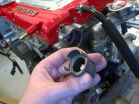
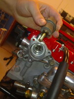
im installing the cam angle sensor but i dont know which way to put it, it can go either way 180 degrees, and the two 'fins' on the rotating part has different sizes.

I searched and read (if i didnt misunderstand) that theres supposed to be an indent on the fin and on the housing, but i cant see any indents or marks at all.

The engine is now at TDC.

Thanks
 

Attachments

  • 15082010138.jpg
    15082010138.jpg
    54.1 KB · Views: 3,709
  • 15082010142.jpg
    15082010142.jpg
    45.3 KB · Views: 2,073
Can I switch to this style CAS with my 96 head? I understand that the pulse will be different but I could get that changed in ECM link right?
The reason why I ask is because I don't want to modify my CAS to accept adjustable cam gears.
 
Brian gave you a picture of an engine off the showroom floor, heres what it would look like in a real DSM'rs engine bay with the engine at TDC. LOL

Updated picture with CORRECT CAS orientation when the motors at TDC.
You must be logged in to view this image or video.


:dsm:
 
Last edited by a moderator:
gofer's picture is incorrect for TDC.

You must be logged in to view this image or video.
 
Last edited by a moderator:
Sax, I'm glad you pulled up that portion of the 2g service manual because I would have never believed you otherwise. I've been driving my car around for years with it like this, I guess what would the symptoms be with this 180* out?

:dsm:

Eric, I'm glad you posted that because it made me go down in the garage and pull apart the CAS and see for myself. Mine was installed correctly but somehow that picture I took of it the things 180* out which is odd, the last I remember I buttoned it up right after that picture.
I put my engine at TDC and heres the (3) pictures proving that Eric and Brian are both correct, that paint marking should align with the CAS sensor.
For fun I spun the CAS sensor in there around backwards and I couldn't even get my motor to start so thats what happens, no spark on 1 & 4 similar to the 1g CAS being 180* out.


You must be logged in to view this image or video.


You must be logged in to view this image or video.


You must be logged in to view this image or video.


:dsm:
 
Last edited by a moderator:
Alright that clears things up, thanks guys!

There is no identification paint on my cylinder, but i can just look at the picture and align mine up that way (and add my own pain)
 
You can hold the cam gear with a 17mm wrench on the other side. My chilton manual says 8.7-11 ft/lbs. I would put a little loctite on it also.
 
sorry to bring this back again but if mine was off i.e 180 out would it cause me to run rich or anything? as i had to take mine out when i did my valve stem seals and i cannot for the life of me find any where in the manual or online where it tells you to take it off and how to reset it again? if at all applicable. the car runs but its the only thing i can think of causing it to run rich! 12.5 on a cruise @25% throttle
 
Last edited by a moderator:
Did you happen to look at any of the posts above you in this thread? There are a few pictures and links that will help you.

I did and ive saved them, but im not with the car till the weekend so im trying to go through my list ive come up with and eliminate the possible chance and this sensor trigger was one that i uad come up a few times in the search

I also thought that being 180 out would cause the rich cruises but if its not then i know to look else where then
 
I removed this with out putting the vehicle on tdc. Any advice?

You must be logged in to view this image or video.


You must be logged in to view this image or video.


You must be logged in to view this image or video.
 
Just like the fact that you were able to take it out, it will go back in but it will do so two different ways. One is correct and the other isn't.
The way you know which is to set the engine to TDC and then line the paint mark up with the sensor like this thread discusses.
 
Just like the fact that you were able to take it out, it will go back in but it will do so two different ways. One is correct and the other isn't.
The way you know which is to set the engine to TDC and then line the paint mark up with the sensor like this thread discusses.
Thanks for the response fellas I didn’t think to put at tdc before removal. The threads stripped out on the sensor portion. I don’t really see paint mark could this be it sorry don’t have the part right in front of me. Also if yo dowel pins on the cam gears point up, it’s at tdc correct!

You must be logged in to view this image or video.
 
Support Vendors who Support the DSM Community
Boosted Fabrication ECM Tuning ExtremePSI Fuel Injector Clinic Innovation Products Jacks Transmissions JNZ Tuning Kiggly Racing Morrison Fabrications MyMitsubishiStore.com RixRacing RockAuto RTM Racing STM Tuned

Latest posts

Build Thread Updates

Vendor Updates

Latest Classifieds

Back
Top