The Central Hub for DSM Community and Information

For 1990-1999 Mitsubishi Eclipse, Eagle Talon, Plymouth Laser, and Galant VR-4 Owners. This is where the DSM platform history is documented and archived. Log in to help us in our mission, and to remove most ads from the browsing experience.

img_8094800x600.jpg

My fuse box relocation (project log)

This site may earn a commission from merchant affiliate links, including eBay, Amazon, and others.

I'm back in school now so just back to working on the car on weekends. Here is my update, although I'm sure I'll forget some things.

I'm still working on the battery relocation but here a few parts of it.

Jegs 300A kill switch and clear billet faceplate (also got the clear billet handle but it doesn't fit right, I'll work on it later):
JEGS 300A Master Disconnect Switch - JEGS
JEGS 10345


I really wanted to make the switch hidden, but I didn't like any of the options I saw and wanted to make absolutely sure this would be track legal. On the street I'll probably just take the handle off so nobody turns power off. Without the handle you would need a pair of pliers to turn it. The clear anodized billet faceplate really matches my car well so it blends in. At the track I'll probably use the normal faceplate so track officials can see it better. Since the clear faceplate doesn't have a hole for the locating pin on the switch I had to cut the pin off.

IMG_7381.jpg


IMG_7376.jpg


Battery box:
Summit SUM-G1231 - Summit® Premium Battery Boxes-Overview – SummitRacing.com

I picked that one because it's a good size, and it just made more sense to go with a plastic box rather than a metal box. Sure, nothing bad "should" happen with a metal box, but unexpected things happen. I really wanted to keep my spare tire too, but there was no way that was happening with this box since I wanted it mounted low. So I got a Harbor Freight spot weld cutter and removed the spare tire and jack supports. Talk about a PITA project, this one had me so pissed off. It was just a pain, and I ended up accidentally drilling through 2 of the spot welds and made 2 pinholes in other holes. So I had to weld them all up, which sucked, and then since my welds sucked I used a bit of bondo to smooth them out. All of the spot welds were grinded down flat. Then I painted the whole spare well so the paint blended in. With the plastic panels back in you don't see a paint line since I painted past where they sit.

IMG_7326.jpg


IMG_7327.jpg


IMG_7330.jpg


IMG_7336.jpg


IMG_7355.jpg


I don't have any completed pictures of that yet. I'll get them later as well as show where the battery box vent hose goes. I'll be using my stock battery for now in favor of cost, and just because the battery is a champ. It's a cheapo battery that has been drained a few times, has been sitting for about a year, and still takes and holds a charge. I like it. Eventually I'll get a closed cell in favor of safety, but this will do for now. The battery was too short for the Summit hold down studs to work, so I had to get new threaded rods, no big deal.


In preparation for paint I removed all my brake lines and clutch line and the prop valve. I painted them to match my car's paint. I also painted some portions of the p/s lines with alumablast, and sprayed a part of the wiper motor that started getting a bit of surface rust with rustoleum. The black parts on the brake lines are the parts that are covered in rubber coating for protection, so I didn't want to paint them because the paint would not stay for long. I did remove one small portion of rubber near where the a/c lines used to go into the firewall. I don't have the a/c box there anymore so I don't really need the rubber on the lines. This was easy to do after heating the rubber up with a heat gun, then it peeled right off.

IMG_8696.jpg


IMG_8686.jpg


IMG_8692.jpg


Since removing the hvac boxes, I had some holes under the wiper cowl that lead directly to the cabin. I blocked them off with some aluminum plates painted to match my car, held in place with clear silicone. This was a very difficult process to install these and seal them up, just because space is tight there. I used silicone because I didn't want anything permanent, or to drill more holes in there. I drilled holes in 2 of the 3 plates and installed grommets so I can run my wiper motor wires through them into the cabin. Here are the holes:

IMG_8712.jpg


And here you can see the plates installed (there is a 3rd plate inside the cabin under the dash not pictured):

IMG_8918.jpg


For the battery wiring I have to run two 1/0 gauge wires through the firewall (one to the starter and one to the alternator). These wires are big (technically they're 2/0 wires) so I had to have some big holes to put them through. I couldn't justify drilling 2 bigass holes in the firewall when I have the heater hose holes nice and empty, so I used them. I had to shape them a bit bigger to fit in two Moroso thru panel connectors. I had to be especially careful while shaping the holes because these connectors are so tight together the plastic parts are touching. On the inside, I couldn't tighten both nuts down because they're so close, so I hacked up a large washer to act as a spacer for the top nut.

IMG_8744.jpg


IMG_8747.jpg


IMG_8755.jpg
 
Last edited by a moderator:
I painted the fuel line and brake lines for the rear of the car too. I couldn't take them out of the car easily, so I did it with them in the car. I only painted the parts of the lines you can see from the engine bay.

IMG_8857.jpg


IMG_8863.jpg


IMG_8867.jpg


Then came time for the bodywork and strut tower repair. I already described all that so here are some pictures. HUGE thanks to my friend for letting me use his garage for painting my car. And even BIGGER thanks to my mom and my little brother who were with me from 4pm to 3am at my friends garage trying to get the bodywork done and the paint on :hellyeah: 
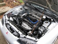
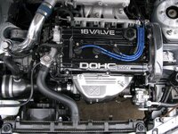
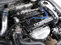
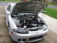
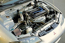
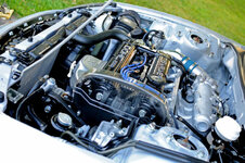
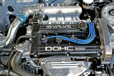
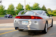
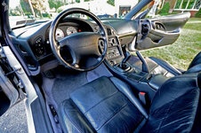
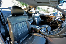
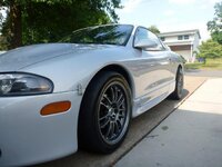
That was a long night...

IMG_8905.jpg


IMG_8909.jpg


IMG_8936.jpg


IMG_8937.jpg


IMG_8938.jpg


IMG_8939.jpg


IMG_8952.jpg


IMG_8955.jpg


IMG_8960.jpg


IMG_8986.jpg


IMG_8991.jpg


IMG_8992.jpg
 
Last edited by a moderator:
Once the paint was cured, I reinstalled all the brake lines. This was a bit tricky to get everything in the right place.

IMG_9002.jpg


97816-my-fuse-box-relocation-project-log-img_9003.jpg


IMG_9009.jpg


Then I painted the subframe and reinstalled that with my new suspension pieces. I now have new tie rods and brake dust shields to go on, and I need to build some adjustable sway bar end links yet. I'm also going to powdercoat a couple more suspension pieces and paint the calipers before the car is done.

97817-my-fuse-box-relocation-project-log-img_9012.jpg


We finally dropped the engine in about 30 minutes before I had to leave for vacation. Pulled an all nighter waiting out the rain, but we got her in.

IMG_9048.jpg


IMG_9049.jpg


IMG_9051.jpg


IMG_9055.jpg


Finally finished my throttle body. This is a one-nippled throttle body that I removed the nipple and had the hole welded shut. Fiav bypass plate from here. SS allen head bolts used for the fiav because I'm tired of those phillips screws. Fiav nipples pulled and welded the holes shut just for the heck of it.

IMG_9068.jpg


IMG_9077.jpg


Plugged the egr hole in the head with a SS 1/8" NPT plug with red loctite on it. You don't need to tap the hole, just drive the plug in. Make sure to drive it in far enough so it doesn't stick out past the flange surface. Intake was installed with a Hondata gasket.

IMG_8899.jpg


IMG_8902.jpg
 
Last edited by a moderator:
Since then I've just been putting stuff back in, did the shifter wiggle fix on my trans just for the heck of it (although the nuts were torqued fine anyway), doing some minor painting, and started working on the wiring again a few days ago. This is how the car currently sits.

IMG_9065.jpg


IMG_9093.jpg


IMG_9102.jpg


IMG_7623.jpg


IMG_7625.jpg


IMG_7630.jpg


IMG_7632.jpg


IMG_7635.jpg


IMG_7639.jpg


IMG_7637.jpg
 
Last edited by a moderator:
That's looking fantastic man! I love the Deutsch harness connector you are using for the bay - it'll make yanking the engine a snap! Your attention to detail and craftsmanship is remarkable for someone with infinite resources, let alone a college student doing this in his spare time.
 
Coming along nicely Eric! Can't believe there was that much rust on the strut tower. Now I see what I have to look forward to. :barf:

Any chance you have a detailed diagram of all the brake lines?
 
Thanks guys!

Erik, what kind of diagrams are you looking for? I don't have any but I could whip some up for you. I just took a bunch of pictures to reference while putting everything back together. The lines are different enough that it's easy to tell what line goes where in the prop valve and abs module (the abs module is actually labeled), it's the actual routing that is difficult (is this line supposed to go under or over this one here?).

Well, after looking over your pics some more it looks like only two lines go into the abs modulator from the master cylinder. Then 4 out, 2 going to the front calipers and the other 2 to the proportioning valve, then the rear calipers. ...Correct?

I want to do away with my abs modulator completely if possible and plumb straight from the master cylinder to wheels at the front or the proportion valve for the rear.

What I'm confused about now how the fluid is being routed from the master cylinder and through the abs hydraulic modulator. I started looking at some diagrams in the FSM and confused myself some more. :confused:

This really shouldn't be in your thread, but if you have any interest taking it to PMs let me know.

That's correct. My abs modulator is labeled for what lines go where, although CAPS says your modulator is different so it may not be labeled, I'm not sure. Here's a picture of the modulator I found in the FSM, although this is not quite how mine is oriented.

untitled.JPG


And here is a picture of the prop valve.

untitled2.JPG


#2 on the modulator goes to #4 on the prop valve, and #4 on the modulator goes to #3 on the prop valve.


If you want to delete abs, see here. In that case, your prop valve would be like this.

untitled3.JPG
 
Last edited by a moderator:
Arg, knew somebody was going to say that!! Try to show off the new shiny nuts on top there and get made fun of for the rustiness!

Ahem,


To do list item #21:
Paint strut tops and tops of UCA and strut studs

;)
 
Yes, I want to remove the abs module entirely. I was looking at the FSM page 3-22 and noticed a picture of the 6 port non-abs proportioning valve. Thanks for the part number. Hopefully the proportioning values are the same. I don't see any details on non-abs cars in the FSM.

What I really want to know is how the fluid from the primary and secondary lines is split. By the look of that 3rd picture with the non-abs prop valve I'd say one line(primary) goes in and splits the fluid between left/front and right/rear and the other line(secondary) is split between right/front and left/rear.

So it looks like no matter what 2g dsm, the primary and secondary lines are to be split diagonally not front/rear from the master cylinder...

I was concerned that maybe the master cylinder was actually split f/r and then went to a diagonal channel within the hydraulic unit. I'm still not 100% sure of the system, but it's getting slightly clearer.
 
Arg, knew somebody was going to say that!! Try to show off the new shiny nuts on top there and get made fun of for the rustiness!

Ahem,


To do list item #21:
Paint strut tops and tops of UCA and strut studs

#22
Replace roll mount nut and bolt

#23
Paint hood prop

;)

Fixed. :p
 
Damn! I was trying to give you a complex. I was going to say powdercoat, but wasn't sure how big the oven is. :)
 
Not big enough for the hood prop or crossmember, they both will have to be outsourced, unfortunately.
 
Add Value - Be Respectful - No Trolling - No Misinformation - Participate Often!
Support Vendors who Support the DSM Community

Build Thread Updates

Latest Classifieds

Back
Top