The Top DSM Community on the Web

For 1990-1999 Mitsubishi Eclipse, Eagle Talon, Plymouth Laser, and Galant VR-4 Owners. Log in to remove most ads.

Please Support RTM Racing
Please Support ExtremePSI

My fuse box relocation (project log)

This site may earn a commission from merchant
affiliate links, including eBay, Amazon, and others.

This site may earn a commission from merchant affiliate links, including eBay, Amazon, and others.

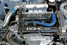
What I really want to know is how the fluid from the primary and secondary lines is split. By the look of that 3rd picture with the non-abs prop valve I'd say one line(primary) goes in and splits the fluid between left/front and right/rear and the other line(secondary) is split between right/front and left/rear.

So it looks like no matter what 2g dsm, the primary and secondary lines are to be split diagonally not front/rear from the master cylinder...

I was concerned that maybe the master cylinder was actually split f/r and then went to a diagonal channel within the hydraulic unit. I'm still not 100% sure of the system, but it's getting slightly clearer.

That is correct, it is diagonally split for safety reasons.


The non-abs info is in section 35A of the FSM. MB895931 is the prop valve you will need, but I'm not sure if the dealer still sells that or any of the lines. ABS cars use a 4 port prop valve and non-abs cars use a 6 port prop valve.

This is the best picture in the FSM I could find of the system. It's a little sketchy, but you can see how the lines travel in the non-abs system.

untitled.jpg
 
Last edited by a moderator:
Wow ive been following this build, i hope one day to reach what you did, over time. I just moved my fusebox inside the car, it was a pain, but kinda fun. Keep up this awesome thread.
 
I've always been hesitant to mess with the wiring on these cars even though I have so many connectors that are no longer used, just hanging from the loom in various places. My first attempt leaving all unused accessory connectors unplugged under the dash only created a bunch of problems - it seems that if you don't plug in the connectors to the switches on the dash, it prevents other systems from working due to the way the car is wired. I ended up having to plug them all in again and just zip tie a huge mass of connectors together under the dash. It looks like crap, but I didn't know the right way to do it.

So in order to do it right, you have to remove the wire (in question) completely? Or is the engine wiring harness different than the harness under the dash? I'd love to remove a bunch of unused wiring and connectors.

Nice job so far Eric. Hope the car works like it's supposed to when you fire it up :)
 
Yep i hope it all works out how you planned it, after my time a few things didnt work i just had a few wires mixed up.
 
Hope the car works like it's supposed to when you fire it up :)

Me too :coy: Before I started, I documented where every wire is supposed to go so I should be good. When I finished the ecu harness I went through and checked every single wire that I touched with a multimeter to make sure the wire went wherever it was supposed to, no problems there. When I finish the fuse box harness I'll do the same thing, and then check the wires that span between the 2 harnesses. I'll check all the systems like headlights, taillights, horn etc. before I fire up the car so that will verify the wires on the fuse box harness. I'm also going to use DSMlink to check everything I can to make sure the ecu wires are right, things like coolant temp, iat, voltage, fuel pump, fans, etc.

I decided not to mess with the dash wiring just because I have enough on my plate as it is. So all my hvac connectors and some others are just electrical taped up for now. Maybe I'll feel like rewiring the rest of the car in the future, maybe not. It's probably not worth the effort, honestly. The main reason for rewiring the engine bay was to pretty it up, but under the dash I'm not as concerned about how it looks :p On a plus note, I weighed the bag of wires I've removed from the car so far - 7lbs.! But from what I've heard from others the dash harness can be a little more difficult because, like you said, messing with a wire can mess with other systems too. In my case I mostly just removed the wire completely. There were maybe a few cases where I had to consult the FSM just to make sure it wouldn't cause any issues.

I'm still not done with the wiring, but here are some pictures anyway. This is what I came up with as the best way to route the wires under the dash. The harness will be loomed of course, but I went through and did my best to make sure the wires would not encounter any area where they could be damaged. I can't wait to finish this harness up for good - maybe this weekend it'll be done.

IMG_7649.jpg


IMG_7652.jpg


IMG_7653.jpg


IMG_7655.jpg
 
Last edited by a moderator:
Wow. I just read this entire thread and I seriously think you should've just had Mitsu build you a new Eclipse. LOL 
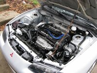
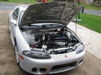
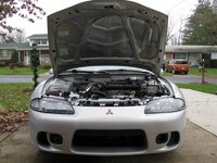
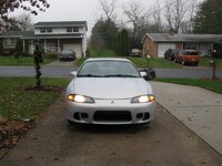
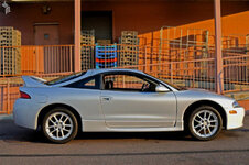
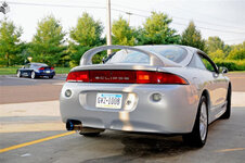
That car looks like it just came from the factory!! :applause:

Props again on the dedication and work. It looks unreal! :applause::thumb:
 
yea holy piss, just spent like no joke an hour and a half to two hours reading all this. It looks amazing. I want to relocate my fuse box in my gsx also simply because i dont have an engine for it yet. So I thought Id clean it up a bit while theres room and time. But I will in no way have this much dedication. Props to you man for havin the patients to do all this work. Cant wait to see the finish product!!
 
Considering most of the cars on dsmtuners are 16+ years old, and how clean a vast majority of them are, I am often impressed with many cars and some members ability to do so much on a budget.

Seeing you two guys put this much work into this car gives me so much hope..I am an 18 year old and I have a 1994 tsi and this is what I dream to do. Pay so much detail to every aspect of the car. I think its amazing the time you put into this car, and how everything is 100 times better then show room quality. It gives me and I am sure many others great inspiration.

Keep up the good work and keep posting!
 
Thanks guys. I probably won't post an update for another couple weeks, bunch of stuff "in progress" but not completed, so I'll wait until I have certain things done. Wiring is done but not tested fully, exhaust is on (although my Megan racing o2 housing and dp don't want to bolt together and I stripped an o2 housing stud that is welded on :banghead:
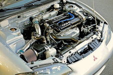
), new tie rods on, p/s on, intake on, intercooler and pipes on, transfer case on, battery relocation 99% done, brakes are 75% done.

Next step is to figure out the pos dp and o2 housing.
 
sweet i had a idea of my tuck, i had to cut it in two places to get what i was after, im thinking about pull the engine out and painting it a neutral color, and follow some of your foot steps.
 
As in... Electrical power? Engine power? Braking power? Power Steering? God-like powers?

F. All of the above LOL

Nah, just electrical power. Hell of a good feeling when we powered her up and everything worked the way it was supposed to. Checked every wire possible we could, plus used ECMlink to check all of the logged values we could with the car off and everything checked out fine. I even bumped the starter a couple times just to make sure it worked ok. Glad I didn't have to the use the fire extinguisher I had waiting nearby :p

I'll post an update with pictures in the next couple of days.
 
Hell of a good feeling when we powered her up and everything worked the way it was supposed to....Glad I didn't have to the use the fire extinguisher I had waiting nearby :p

I can SOOOOOO relate to that. I must have run over 1000 things in my mind that I might have forgotten when I rewired everything.

When I turned the key on and nothing went pop, and everything looked good in ECMlink...I figured I must not have something hooked up right. Once I was convinced that it really was working ok (after running around the engine bay in a panic, extinguisher in hand), I pretty much walked around on air for a while. I think I sat in the car for 3-4 hours over the next couple of weeks just listening to the stereo....happy the car had a working brain again. LOL

Wait 'till it starts up on the first crank...you think you're happy now... ;)
 
My battery relocation is finally complete.

Parts list:
JEGS 300A kill switch
JEGS clear anodized billet faceplate
(3) JEGS 1/2" terminal guards
Negative battery terminal
Positive battery terminal
(6) 3/8-in Stud Terminal Insulators
2/0 Red/black battery terminal insulators
Triple-wall adhesive polyolefin heat shrink tubing tubing
Terminal Solder Slugs
Heavy-duty Tinned Copper Lugs
Tinned Copper Crimp Lugs
(2) Moroso Thru-Panel Battery Connectors
Summit Racing black battery box
KnuKonceptz Kolossus Fleks Kable 1/0 Black Power/Ground Wire - purchased 50ft. and used ~44ft.
KnuKonceptz Kolossus Fleks Kable 4 Gauge Black Power/Ground Wire - used ~4ft.
KnuKonceptz KonFUSED 3 Way Distribution System - all three 150A fuses
KnuKonceptz In-Line Waterproof ANL Fuse Holder w/ Fuse - 200A fuse
(2) XScorpion Circuit breaker - 200A
McMaster PUSH-IN FLEXIBLE RUBBER GROMMET, MS 35489-27, AN 931-24-28, 1-1/2"ID,2-1/8"OD - P/N 9307K84
Reusing original battery for now

Tools:
Solderless Connector Crimping Tool
Liquid Flux
Cable Cutter
Rotary Cable Stripper


1.gif


1 (Large).jpg


2 (Large).jpg


3 (Large).jpg


4 (Large).jpg


5 (Large).jpg


6 (Large).jpg


7 (Large).jpg


8 (Large).jpg


9 (Large).jpg


10 (Large).jpg


11 (Large).jpg


12 (Large).jpg


13 (Large).jpg


14 (Large).jpg


15 (Large).jpg


I don't have any good pictures of the cables in the engine bay or the fuse box cables to the distribution block right now.


The pictures pretty much sum it up but I'll make some comments. The spare tire and washer fluid bottle brackets were cut out of the trunk to make room for the battery box.

The cable I used looks to be good stuff but it is so big it is actually 2/0, not 1/0ga. This means I had a tough time finding all the lugs and parts I needed. Some lugs I got had to be crimped then soldered, others I could use the solder slug system on. The reason for this is because I always matched the bolt hole in the lug to each place it was bolting to - no "one size lug fits all" here. If you're really interested in the lugs let me know and I'll try to remember which size worked for each spot. To see the solder slug installation watch this video:
YouTube - The proper way to solder battery terminals

For the copper crimp lugs I couldn't use the solder slugs, so I had to crimp them using the tool listed above. After crimping I heated the lugs with a torch and shoved solder in until it was full. Both methods worked equally well IMO.

Triple-wall adhesive polyolefin heat shrink tubing tubing is the sh*t. Nuff said. :thumb:

At first I got Taylor battery cable terminals, but my wire was too big to fit in them. Then I got 2/0 ones from McMaster that looked identical to the Taylor ones. However, they are both Universal fit and I didn't like that. So instead I bought the ones listed above that are specific to (+) and (-) terminals (which are different sizes) and I like the fit better. All 3 sets looked identical otherwise.

The circuit breakers are kind of a no-name brand. They were the best 200A ones I could find. I bought Stinger circuit breaker covers for them, and they would have fit with a little modification. However, my lugs were so big I would have had to cut out quite a bit for them to work. I liked the terminal insulators better so I used them.

The kill switch is heavy and big. Be warned, but it does look like a quality piece.

The 1/2" terminal insulators were used at the kill switch and both sides of the thru-panel connectors. The 3/8" ones were used at the circuit breakers, alternator, and starter.

One circuit breakers is mounted to the battery box. I had to use slim head flanged allen fasteners on the inside of the box to provide a full adjustment range for the battery tie down (McMaster P/N 92137A535). The other circuit breaker is bolted to a stud on the rear of the car. Only one mounting point is used. The fuse and distribution block on the firewall are mounted with heavy duty velcro. Couldn't think of a better way without putting holes in the firewall.

The little plastic things under the kick panel where the wires run had to be trimmed on the bottom because the wires are so thick. Took a minute with the Dremel.

The trunk plastic panels still fit fine, they just weren't on for the pictures.

The battery grounds on the drivers frame rail (pictured).

To get the wires to the kill switch, I used a factory hole in the rear of the car. I believe it was about 1.3" or so from the factory, and I used a hole saw to drill it out to 1.75" to use the grommet listed above. The factory wires still go through this hole along with three 2/0 wires. Drilling through this metal was kind of tricky with the hole saw because I had to start with an existing hole. I ended up grinding it out with a Dremel until it was 1.5", then I bolted my 1.75" hole saw on the drill then my 1.5" hole saw backwards to act as a guide in the hole. While drilling the metal tried to tweak because it is so thin so be careful.


I think that's way more info than any of you wanted, but ask questions if you have them.
 
Last edited by a moderator:
The wiring harness is also done. I ended up adding 12 new connectors from Ladd Inc. The fuse box has 3 (1 pin DTHD, 4 pin DTP, and 31 pin HDP20), one is just for the injectors (12 pin DT), two each just inside the cabin at each fender (4 pin DTP and 31 pin HDP20), one inside the firewall for the ecu harness (47 pin HDP20), one just for the windshield wipers (6 pin DT), and two go between the ecu and fuse box harnesses near the ecu (12 pin DT and 12 pin DT). The picture below is the harness laid out like it goes in the car, and the new connectors are circled.

1.jpg


There are multiple connectors at some points because I had a few large gauge wires that wouldn't fit in my main connector. I also upgraded the headlight wires to 12ga. in case I go with HID's in the future. I needed a connector for the windshield wipers because I routed it through plates I made that used to be for the cabin air intake. The clutch cut wire for dsmlink was routed along the dash harness that I did not modify, and from there goes through a factory connector to the ecu harness. I had some spare wires laying around that had the right pin on the end to fit in that connector. The knock sensor and o2 sensor wires were a little tricky to get through connectors because they have a shielding wire inside. I had to use a separate pin for the shielding wire and keep it right next to the other wires when going through the connector. A little bit of heat shrink on the shielding made sure it wasn't exposed. The fuse box uses two 4ga. wires to get power from the distribution block.

2.jpg


New tie rods.

3.jpg


Powdercoated the ecu.

4.jpg


Powderocated a few more parts in the engine bay and put them in. More things have been put in the engine bay since this picture, but this is pretty much how it looks.

5.jpg
 
Last edited by a moderator:
I see you got the clear cover for the cams, where did you get the battery cable that looks heavy duty, im asking because im doing a new wiring project.
 
Support Vendors who Support the DSM Community
Boosted Fabrication ECM Tuning ExtremePSI Fuel Injector Clinic Innovation Products Jacks Transmissions JNZ Tuning Kiggly Racing Morrison Fabrications MyMitsubishiStore.com RixRacing RockAuto RTM Racing STM Tuned

Latest posts

Build Thread Updates

Vendor Updates

Latest Classifieds

Back
Top