


We're on Boost
15+ Year Contributor
- 2,992
- 1,436
- Aug 25, 2007
-
Seattle area,
Washington
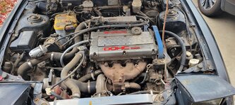
That should be ok then, if he is going to help you with it.Yes the shop I’m taking it to is actually a family member of mine. See I was thinking it would take some time also but he’s very reassuring we can knock it out in a day if I come in the morning. Worst comes to worst he said it can sit until we can get everything in but he’s very firm it won’t take long.


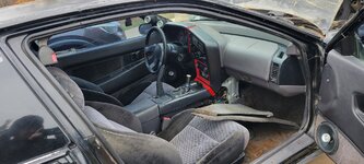
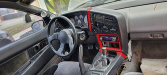
 . It's easy, there are only 4 screws holding it on, but the hood release cable comes down with it so you can't just take it out of the car, and you can't just lay it on the floor either because the cable isn't that long, you have to have like a little cardboard box or something to set it on in the footwell to keep from risking damage to the hood cable.


