
- Thread starter
- #651
turbosax2
Moderator
- 4,482
- 673
- Nov 19, 2006
-
Mechanicsburg,
Pennsylvania
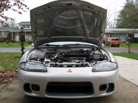
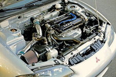
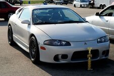
Eric, are you still using your power steering?
Yes.
For 1990-1999 Mitsubishi Eclipse, Eagle Talon, Plymouth Laser, and Galant VR-4 Owners. This is where the DSM platform history is documented and archived. Log in to help us in our mission, and to remove most ads from the browsing experience.

This site may earn a commission from merchant affiliate links, including eBay, Amazon, and others.


