The Central Hub for DSM Community and Information

For 1990-1999 Mitsubishi Eclipse, Eagle Talon, Plymouth Laser, and Galant VR-4 Owners. This is where the DSM platform history is documented and archived. Log in to help us in our mission, and to remove most ads from the browsing experience.

1991-Mitsubishi-Galant-jdm-front-bumper-03.jpg

GSTwithPSI Galant VR4 1837 of 2000

Mitsubishi Galant VR4 number 1837 out of 2000 imported in 1991

This site may earn a commission from merchant affiliate links, including eBay, Amazon, and others.

@We're on Boost

Traction will always be an issue, even with a welded differential. A welded diff only ensures the front and real wheels turn at the same speed. Actual torque distribution (which is what's important here) will depend almost entirely on traction. Torque split is determined by your differential gearing, whereas the actual torque distribution will depend on traction available.

The best differential would be one that matches weight transfer.

The welded differential is popular mostly because it reduces the chance of a breakage, not so much because it maximizes traction.

There's a good write up which explains these principals more in-depth: http://www.dsmtuners.com/threads/awd-dsm-torque-split-distribution.410949/
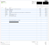
 
These showed up in the mail today. Now, I should have the fuel needed to push this 68HTA V2 to its limit. I'm pretty excited to get them in the car and get the tune dialed in.

N1789oLOsvVgqX6wX_SgZqI7HqrsgR214KGse40i-CIOpdYE1jPdUTWs4DUTR0IwE-qOwfM9mcoJ60cg3w=w1218-h685-no.jpg

xwK2zyH9cfPxDBXtY9dLDycJPHEe9O94SYCO-J5CUc1H1fgZb0Uen4CvSZwykpgGpyKdhxSSwZrEWajOnA=w1218-h685-no.jpg

q8zW0rJdjhCX76XaH51eK-08LSxcB9kKZzc0wcWD0169uzTHT3i_Ky5nDmJIPBCmfAWl-ILheSN4aSXNFQ=w1218-h685-no.jpg

htfa84LruxXUO-eGJ1JBFZ6ap6lQNNnmtyMSmAayyvP1A7T_fFPBRezo_O9oN_zq3y7ifHJTfO8=w386-h685-no.jpg

KETsfgt0Rqosfwnw0ZxqW-pNNIqYtNCcK3tvhmEdBh5B-p7LA-jz8sJPjxI1zdP5vIn48jcKsZvdV5-KWw=w1218-h685-no.jpg
 
Alright, 1650s are in, and the tune is mostly dialed in. I have a bit of work to do to the VE table during spool up, but the car is running great.

First impressions of the 1650 High-Z injectors are AWESOME. Amazing driveability, and superb performance up top. Idle and cruise are smooth as butter, and I'd think the car had stock 450s in it if I didn't know any better.

vhkB3UCGewwTnETt1CJoMHnNUOR-aDvl7p4sfhyzr6ekfFiJlCZoMzZiVLV3vWT1znnEzXfDwFt1KaIggQ=w1218-h685-no.jpg


upload_2016-11-19_18-30-48.png
 
Last edited:
Getting close! Already running out of injector again :rolleyes:

upload_2016-11-21_19-0-1-png.319029
 
Getting close! Already running out of injector again

Gee that seems impossible. Seems more like it would be the fuel pump running out.
Is it still a single Aeromotive 340 E85 stealth fuel pump?
That would only be good for about 225 lph at 80 psi (50 + 30).
Doesn't seem like enough on full-blooded E85.
The injectors can handle way more than that.
I'm having trouble finding a flow chart for the new E85 compatible version of the Stealth 340 though. So I'm looking at the chart they have in the installation instructions for the 111xx series Stealth 340. The flow chart is probably still right, but if you know different, give me a holler! https://www.aeromotiveinc.com/wp-content/uploads/2013/08/340-Stealth-Intructions-08-13.pdf
 
Last edited:
Yeah, I'd concur with your math. I have the Aeromotive 340 LPH E85 Stealth Fuel Pump (11542) which according to Aeromotive's chart, flows ~225 lph @ 80 psi. If my math is right, I need closer to 380 lph. The crappy thing about bumping BFP (resulting in higher overall fuel system pressures) is it also decreases flow.

HP estimates for the FIC High-Z 1650s indicate I should definitely have enough injector, I was more being sarcastic with my comment. I believe I still have some fuel system deficiencies to correct before I get the car completely sorted how I want on E85. Less boost is obviously not an option...

upload_2016-11-22_14-57-37.png


https://www.google.com/url?sa=t&rct...sg=AFQjCNGAIEyzQjQ-ZvukhcIfLvNCRW_rRg&cad=rja
 
Cool!

Yeah, higher base pressure decreases the capacity of the pump. I suppose people got into doing higher base pressure as a work-around for when they had injectors that were too small. And you might get better atomization.

I don’t think you will need 380 lph though. Not yet anyway. Because my fuel system can only do about 288 LPH at 75 psi, and that worked apparently fine for the 650 awhp dyno tune you see in my profile. The 288 number is not from ER, they don’t know. That is something I figured out, and then with the help of somebody here in DSMtuners, low and behold, I found bench test results that had been posted by AMS several years ago which agreed with the 288 number for 2 Walbro 255 pumps in series, at 75psi. So I’m fairly sure about that number.

When ER proposed that pump system for my car, I was very skeptical that the flow capacity would be enough for my target of 650 hp on E50. But ER was 100% positive that it would be, they’ve done it a gazillion times. That run was actually on E60, and that is AWD Dynojet horsepower.

I really like the idea of the 2nd pump not even being powered at idle and low load. That way you don’t have so much return line flow, and there is less drain on the alternator. It only kicks in by a boost activated switch, and relay. The rest of the time it is just a slight flow restriction to the flow from the intank. The Wally 255’s are gerotor positive displacement pumps, so I believe they are actually rotating, as the fluid from the intank pushes through them. ER mounted the inline on the firewall.

Well I’m not trying to sell you on the idea of doing it that way, but I thought it would be worth bringing up. I just kind of noticed today that if you were to add an AEM 380 inline to your Aeromotive 340 intank that you already have, in series, you would have about 370 LPH capacity at 80 psi. Since the pumps are not equal, it would materialize like this: At 80 psi, there would be about 30 psi across the Aeromotive, and about 50 psi across the AEM inline. Golly 370, that’s pretty near your 380 number LOL. AEM says their 380 will have shorter life if you use alcohol fuels. The Wally 255’s are not claimed to be E85 compatible either, but ER says it’s no problem with the Walbros. Anyway, there are some thoughts about the series pump way of doing it.

___________________________________________________________________

Oops, actually it was TED B in Evom who showed me the AMS chart, but it has probably been posted in DSMtuners also. Anyway here it is:

Walbro fuel pump flow charts by AMS, showing 255 intank to external 255 series and parallel.jpg
 
Last edited:
I used the deatschwerks calculator below to get 380 lph. I've used it in the past, and it's always been accurate with how my setups performed: http://www.deatschwerks.com/fuel-calculators/fuel-pump-calculator

upload_2016-11-23_9-48-12.png


The problem with running pumps in series is you don't really gain flow. Two pumps in series running at the same time would produce twice the pressure at the same volume. Meaning, a system with two Walbro 255 lph pumps in series can only flow a maximum of 255 lph. Where your setup shines is under pressure, since, as boost increases the two pumps combined in series can maintain consistent flow at high pressure. To actually increase flow, you'd need to run dual pumps in parallel.

I do appreciate the conversation, and suggestions. I'm still considering my options, and trying to decide what the best approach is for my setup.
 
Last edited:
The injectors will support more HP at higher pressures, given you have enough fuel pump.
 
I used the deatschwerks calculators too – both of them!

The calculator you show is really nice for calculating the pump flow rate required to max out a given size injector, and what you show there I believe is right for that. But it says nothing about how much power you would be making at that amount of fuel flow. For that you need a different calculator.

What I meant by not needing 380 LPH at 80 psi *yet*, I meant with your current turbo, which doesn’t have that much capability. But for future, larger turbos, different cams, etc, yes it would make sense to have a pump system that can max out those beautiful injectors. I don’t have that. My pump system can’t max out my injectors. But I'm never going to go beyond where I'm at now, with turbo and so-forth. So it's ok.

The "other" calculator is the deatschwerks “Fuel Injector Calculator” which I’m sure you have seen. It is for estimates only, rule of thumb type stuff. I kind of like this calculator, but there may be others that get you there more directly.
 
Last edited:
Looks like the “perfect storm” of conditions for an alternator fire was even more “perfect” than I thought. I verified for sure that there was a slight fluid leak from the power steering pump – from the high pressure fitting on top of the pump. The alternator is in the stock position (not relocated) so it is directly underneath the PS pump. I suppose a few drops of fluid fell into the alternator on my “perfect storm” day and caused the 5 seconds of black smoke and the dead alternator.

Looking inside that fitting, I found American Standard 1/16” o-rings. I don’t know what the factory spec is for those o-rings but 1/16” looks wrong to me. 2mm looks right. So I put in 2mm metric o-rings, with MolyKote 111 silicone compound. It’s wonderful now.

One clue was that the alternator started working again about 2 days before Halloween. I’m calling it “The Zombie Alternator “. Glad I didn’t put the beautiful new Bosch alternator in right away. It would have got dripped on too probably.

Before this discovery, my “perfect storm for an alternator fire” consisted of a hot day, huge traffic pileups at the traffic lights which were out because of a region-wide power outage, all the new heat-radiating stuff in the engine bay with no heat shield on the PS pump or the alternator, 3 fans putting load on the alternator, and no cooling loop for the PS fluid (it was removed as part of the FMIC install). Wow.

(Edit) The factory manual says that those 2 o-rings should be 1.9mm rather than 2mm.
So I'm going to say that 1.9mm should be the way to go.
1.9mm x 11mm and 1.9mm x 13mm.
 
Last edited:
I've got lots of exciting stuff in store for 1837!

I'll start with my fuel situation. I recently upgraded to FIC 1650s, and believe I'm running out of pump @ 30PSI. So, I picked up an Aeromotive A1000 to run in series with my in-tank Aeromotive Stealth 340. I got everything installed, and flipped on the system to check for leaks. Sadly, the A1000 was slightly leaking fuel from the power terminals. So, I pulled it off and sent it in to Aeromotive for service. I'm hoping to have it back sometime next week.
NluqeDxBHvPm_gdwuChOYOGnuZy_4Vj13QNtZ6WXExvcMhPedxnkXrDXwTACeFm5VncHHVAY_JpEx3nZCA=w1218-h685-no.jpg


Next up, drivetrain upgrades! I finished picking up the remaining parts I needed to install my Shep trans. I'll be swapping in an ACT release bearing, as well as a new Competition Clutch forged steel release fork & pivot ball. I also grabbed some solid shifter base bushings to make shifting a bit crisper. Hopefully, all this combined with the stage 2 Shep trans makes for some quick shifts.
e_7LUaJtXVGyap43C2D3dzvWfKS4vEgOkKybvzZ6sUTAKtSufr_sRlihSlX3qd4GufIpL0AYYbRlJYIjww=w1218-h685-no.jpg

N48mXnWGVhcLWVqegcEGY-HIvDZxZRVlYGdVXaDocKLrom7TGijdjH4rsx6LlzwBemn6vpPkjEdzaLFjjQ=w1218-h685-no.jpg


Last but not least, future turbo setup: FP3052 and Tial 44mm wastegate :D
ZRHJOazp9y33f84iqodNIHq-Tvkq1l91GfWXPfiFQAgdBh_X3bg06PZ2qa2k8TmhiFXTs2zN6Z2QN4REvg=w1218-h685-no.jpg


Now, just have to find time to put all this stuff on...
 
Wow, that’s an interesting combination of fuel pumps. Do you know anybody who has used those particular pumps in series?

One possible problem could be cavitation in the A1000 due to not enough supply from the 340.

The idea being: The 340 can flow close to 450 LPH at 0 psi, which is a lot, but it’s a little less than the A1000 will want when rail pressures are low (low load). So theoretically there could be negative gauge pressure in the line to the A1000, until you get on it and the boost and fuel pressures go high. I don't know, maybe a small amount of cavitation at low pressures is not much of a problem. I'd be wary of that though.
 
@We're on Boost

No, I don't know of anyone running this combination of pumps. The 340 is the largest in-tank pump Aeromotive offers, and I don't think the A750 will get me to where I need to be. I'm keen on sticking with Aeromotive pumps, so, the 340/A1000 combo will hopefully do.

I've done quite a bit of research on this setup though, and think it will work out fine. In addition, I've been working with Aeromotive's tech support, and have bounced my plan of them as well. They are in agreement that this combo should perform.

As a general rule, Aeromotive recommends only combining pumps in series with a differential in flow of around 10-20% max. Given the flow charts below:

The Aeromotive 340 should flow approximately 320lph @50psi.

The Aeromotive A1000 should flow approximately 625lbs/hr (~390lph) @50psi.

If my math is correct, the difference at BFP is right around ~20%. I'm no engineer, so I'm only confident in my ability to do the basic number crunching. But, based on that, I don't see where there would be an issue here. If you do, please, let me know.

p-1616-11101-chart.jpg

upload_2016-11-22_14-57-37-png.319067.png
 
I’m glad you talked to their tech support – that is something I was going to suggest. Because it’s a little risky to be the first person to try a particular pump pairing. But if they think it’s ok, it will probably be ok. Usually the support people for a manufacturer are pretty cautious about these things, and they should be LOL!

It looks like you are using the same calculation I am for converting lbs/hr to Liters/hour, so that is good.

Also the suggestion they gave you of 20% for the maximum mismatch, I think that is a good rule of thumb.

But I have trouble with their chart for the A1000. What the heck, is that a chart or a cartoon? A real chart would have tick marks along the vertical scale and the horizontal scale, and there would be a number clearly associated with each tick mark.

On this A1000 chart, there are no tick marks, and the horizontal lines they draw across the chart don’t line up with the numbers on the vertical scale, and in fact the spacing between those lines and the spacing between the numbers isn’t even the same. The “200” is in the middle of its space, and the “1000” is near the top of its space. Disgraceful. I would flunk the guy that made this chart. So I wouldn’t swear that I know how to get correct numbers off this chart. This is like what companies sometimes throw out there for the general public, but no engineer would actually use a chart like this for design purposes. LOL!

I can see how the 12 volt line could be near 625 lbs/hr, but the 13.5 volt line is at about 790 lbs/hr, and I would think you’ll have 13.5 volts there, especially with that nice alternator. That’s about 500 liters/hour, so the 20% is kind of out the window, unless you are doing something to reduce the voltage to the A1000. 500 is about 50% more than 320.

That 500 LPH is why I said that the A1000 will want more flow than the 340 can pump even at 0 psi (about 450 LPH). That is how you could have negative gauge pressure in the line to the A1000, which could cause some cavitation in the A1000. I don’t really know that this is a problem. But it is pushing things kind of far, and if you were within that 20% rule of theirs, you could be a lot more confident about it.

The basic analysis of 2 pumps in series goes like this – there are 2 conditions that have to be met for each point on your new graph:

F1=F2 (this means there is the exact same flow rate through each pump, at any given instant)

and

P1 +P2 = Po (this means that the pressure across pump 1 plus the pressure across pump 2 equals the pressure you get at the outlet of the inline pump).

You get the chart for each pump in front of you on the screen, and you look for the point on each chart that satisfies both of these conditions. Do that for each Pressure where you want an answer. When you do this you can make a whole chart if you want, and if the intank pump is a lot smaller than the inline, at some point as you go to the left, there is no point on the intank chart that satisfies F1=F2, because that point is off the chart (to the left). In this case you’ve already run the intank pump off the chart at Po=50 psi.

That explo is probably a little hard to follow, but if you look at the numbers I posted a few weeks ago for the AEM 380 in series with the Aero 340, I gave some numbers that you could back-engineer for an example.

When I wrote AEM about a year ago to ask them about using their 380 in series with an intank, the answers I got back were pretty brief, but it sounded OK. Except they didn’t like the idea of switching it on and off like my system does. They didn’t think that would be very good for the intank pump. “Not recommended” they said, because of heavy restriction from the 380 inline when it is turned off. They did say it would be fine to switch it back and forth between 10 volts and 14 volts. I didn’t push them for any more info because ER for sure wanted to turn the inline on and off.

Fuelab, wow, I had a long email chain with an engineer there who told me some stuff that was really interesting. That was Rob Scharfenberg, Chief Engineer, Fuelab. But the Fuelab inline is slow turning on: “Fuelab pumps require typically one to two seconds to start and begin flowing, due to the electronics inside and a limitation due to "sensorless drive". If a pump is to remain off during "low engine demand", then it must be started at least two or three seconds PRIOR to it being needed.” Now I would have never guessed that if I hadn’t talked to Rob. If you want to do that you kind of need to do it with their PWM speed controller, and rather than switching it totally off, you just run it at a real low pulse width when you want less flow/lower pressure. Then when you kick up the pulse width, the pump responds very fast.
 
Thanks for the feedback! I'm definitely getting what you're saying.

Admittedly, I only did my calculations based on the lower voltage A1000 pump curve. I definitely agree the disparity between pumps only increases as voltage increases.

Also, I agree the chart for the A1000 isn't terrible intuitive. Even the 340 chart is meh.

I'm basically using the numbers to get a general idea as to whether this will work or not. I may end up bumping down to an A750 if the A1000 turns out to be too much. Given all the variables, I think I'm going to need to do some real world testing to really see if this is going to work successfully or not. Things like actual pump voltage, and even line size are things that haven't even been factored in yet. Not to mention, we are both assuming the flow charts available for each pump are accurate...

Again, appreciate your feedback. I'll be sure to post updates about how this does or does not work out.
 
Hmm, I’ve never looked at the A750. Cool, let’s see how that comes out.

So the question with the A1000 was “Is it too much?”
And the question with the A750 would be “Is it enough?” (Because it is actually smaller than what you already have in the tank.)

Wow, they’ve improved their chart making skills, a little bit. The numbers on the vertical scale actually line up with the horizontal lines!

Ok, so I’m going to wiggle-in on the area around 90 psi total (at the outlet of the inline pump). That’s Po in my equations above. That process is shown by the first 3 rows of numbers.

The 4th row is a check at low pressure to make sure the max flow will never exceed 690 lbs/hr. Beyond 690 I figure the A750 is uncomfortable. I picked numbers that came out to 28 psi for that, plenty low.

Going to start with 340 LPH flow, get the psi for each pump at that flow rate, that’s the first point, and go on from there. Here’s my chart:

Aero 340 intank in series with Aero A750 inline charted for 90 psi and idle.JPG


And there you have it. Those 4 points are enough to make a whole chart for this pump combination.

So the bottom line is, with 90 psi at the outlet of the inline pump, you’ve got about 310 LPH of flow, at 13.5 volts. The 340 is doing most of the work, as expected because it is bigger.

The check at 28 psi came out to 620 lbs/hr which should be fine for the A750 to handle.

I picked 90 psi as the high pressure target because that’s fairly generous. It could let you have 50 psi base pressure + 35 psi boost +5 psi pressure drop in the lines and fittings.

310 LPH at 90psi is actually pretty decent. My system of 2 Walbro 255’s in series will only do 280 LPH at 90psi, and that is at 14 volts. It’s enough for me but I’m only running 60% ethanol max. And the 340 intank all by itself only does about 210 LPH at 90 psi.

Anyway that’s how I chart one of these series combinations.
 
@We're on Boost I'm not following where you're getting the pressures you charted for the A750. Perhaps we're looking at different flow charts?

According to the chart I found, the pressures for the A750 at the flow rates you identified are as follows:

(lph) lbs/hr @ PSI

(340lph) 540lbs/hr @ 11 PSI

(300lph) 480lbs/hr @ 23 PSI

(310lph) 493lbs/hr @ 21 PSI

(390lph) 620lbs/hr @ 0 PSI

upload_2016-12-19_20-4-10.png


I charted this out for the A750 previously, and deemed it inadequate at high pressures. Am I missing something?
 
Yes, your numbers are right on for the 12 volt curve. My numbers are coming from the 13.5 volt curve. I think that if you are getting close to 14 volts at the battery terminals, and if you have 10 gauge or even 12 gauge wire to a relay, and again from the relay to the pump, you'll probably have about 13.5 volts at the pump terminals. The resistance (ohms) per foot of wire in the 10 gauge or 12 gauge size is very low. You won't lose much voltage if you have it wired that way. V=IR, one of the most amazing and useful equations in all the universe!
 
Ah, I suppose I should have read the note at the top of your chart...
 
With the A1000 though, I wonder, if it is doing anything bad like cavitating, you might be able to hear it. If everything else is turned off, engine off, fans and everything else off, if the only thing running is the fuel pumps, you could probably hear cavitation. Don't really know. Other than hearing it I'm not sure how else you would know.
I am thinking, if you can't hear it, then it's probably not bad enough to do any damage. Because cavitation should normally cause vibration/noise.

Another positive note: Reading through the install instructions for the A1000, and their web page for the speed controller they offer for it (16302), plus tech bulletins 301 and 302 for the speed controller -- Many many many of the things they tell you to do, or warn you about, are predicated on the idea that you are running the A1000 all by itself, with no pump in the tank. And those particular items, you won't have those problems, or they will be less, when you are feeding it with a pump in the tank!

This is what English Racing calls "a science project" LOL.
 
Last edited:
A few updates...I finally got my pump back from Aeromotive. After I shipped it in they inspected it and recommended a full rebuild. Apparently, a full rebuild just means they ship you a new pump for $210 bucks, so that's pretty legit I guess.
n3JEqjuP6IxuKMYnzp37GClis5mMyLkm25PvU73tcRBViABwc9wNezn1OpDIwfvmxEBEFt8awSOeNAERRg=w1218-h685-no.jpg

pMyx5DAZbCRX2NU2A5E5q0Goxxen6vqGaYl6YoB3IMvJwDKTIqschgbOBLjAbQ-Oz0H7IpfGCX5fvGJI7Q=w1218-h685-no.jpg


Here are a few shots of the install. It fits great right behind the driver side rear bumper panel.
x4vnfsVb9Ji75sT7FiFrogFpZ6e4Orf9OyNNUn034XzDA1Pxs0BDl1wJArId5Hj3C3psSkKG0i-O1bHtoPU=w386-h685-no.jpg

OfQqBhr7tMIvyboGuMOiipzpd-2dvNJ5_xE3ZICrPdo04e9Ee-2T7xS82V6F6hi1XKJN7xmaDKvVHZpJhE=w1210-h685-no.jpg


Initially, I thought the 340 would be enough to feed the A1000. But, after crunching some numbers (thanks for the help @We're on Boost), and doing some testing, I figured out the single 340 wasn't going to cut it. So, after contemplating what to do about about it for a while, I ended up building a dual in-tank setup. I picked up another Aeromotive 340, and modified a stock hanger to to fit the pair.

I'll start by saying, there's no sexy way to do this. The hole in the tank really limits how the pumps can be configured. The pump strainers are the biggest obstacle, and they basically determine how the pumps can be clocked. After playing around with a few configurations, I got one that worked well. The second pump has to sit slightly below the first with the strainer clocked under. I attempted to make a nice bracket to hold each pump, but found out again space limited what could be done. There's a reason people use hose clamps, because they're basically the only thing that will work...

I've seen people use the Y hose barbs, but I think for the volume of fuel being moved by most dual pump setups, that's not really sufficient. Each pump has its own outlet on the hanger. The outlets are -6AN, and get routed to a Y block with an -8AN outlet which feeds the A1000.
I2GihdSCibvMAWeM7bIt3plFlQeKL83fLcKAk42Yv-jQR3JORLiFeB9ZMicPszP9sg0jcSHF3biUYfGeEQ=w1218-h685-no.jpg

ssazOrRwwBNpP_E93HHE1pttN4Nowh9KEGVyBv9XsCRA5LDcK6m9YdhwRVpNurrVYieubeXnmcXo2C-N-qk=w386-h685-no.jpg

Bh_GZwTuDjDofZu5dQIaohUXCUxDF6PnCnkFeyQ1Y1StL5G_agAlhDh1FN-avXn1SJ9CRLTP0RBHES7aJVI=w386-h685-no.jpg

x1GoV8SKsna7MB_vClDnW19J6caf2s9oVcKoXfIPf6LyYVzYXbp7k2zOpz3ZoLOQFqrjt16vrXRk_RZi4T0=w386-h685-no.jpg

lJe8HhoQDkpgnm8hMAGKrNI5ZTk0XrfUTPopCt71FZiDzXUajTFWVdCPvC1Jhu74xJo9uCgA6kJSwtmNQ7c=w386-h685-no.jpg

7wovFCuUiVk9wKPsu9EhXW1gQQ2yfRJamLMYOcvnCD11D5voHigK6hvwjuDWKaBMomFd8E2yudaWBCwyiU=w1218-h685-no.jpg


I got everything installed and snugged up, then used ECMlink to switch on the system and check for leaks. Everything is sealed up tight, and seems to be working great. I will say, this thing is pretty noisy in comparison to the old single stealth pump (hence the name, I guess). The car sounds like a spaceship on start up. By the time I finished up, it was pretty late, so I'll go out for a test drive tomorrow and start working on re-tuning the car.
 
Last edited:
Add Value - Be Respectful - No Trolling - No Misinformation - Participate Often!
Support Vendors who Support the DSM Community

Latest Classifieds

  • For sale 2g 2G Mishimoto Radiator & Fan Shroud
    2G Mishimoto Radiator & Fan Shroud $200 + shipping and paypal feesYou must be registered to...
    • jersygsx
    • Updated:
    • Expires
  • For sale VIRGIN 4G63 6-BOLT TURBO HEAD
    Came off a virgin stock AWD Auto 1G DMS (91), also have matching block and crank which are also...
    • The_Partout_Spot
    • Updated:
    • Expires
  • For sale 1G DSM 4G63 6-BOLT TIMING COVER
    Used, see condition in photos. Buyer covers shipping / fees.
    • The_Partout_Spot
    • Updated:
    • Expires
  • For sale Garage clean out
    Changing setups on the car and getting rid of some stuff as well that's been laying around. Will...
    • 92GSXtacy
    • Updated:
    • Expires
  • For sale 4G63 Griffin intercooler cores
    Griffin intercooler cores. Top to bottom flow. High cfm and heat transfer. 24x8x2.75 and...
    • Galant665
    • Updated:
Back
Top