The Central Hub for DSM Community and Information

For 1990-1999 Mitsubishi Eclipse, Eagle Talon, Plymouth Laser, and Galant VR-4 Owners. This is where the DSM platform history is documented and archived. Log in to help us in our mission, and to remove most ads from the browsing experience.

20231029_160050.jpg

My old highschool car

I regret getting rid of this car but have it back again!!!

This site may earn a commission from merchant affiliate links, including eBay, Amazon, and others.

I do not know where anything is set. I adjusted the fuel injector size to stock 450 and did the fuel calculation on dsmlink, outside of that I havnt adjusted anything and trying to learn dsm link as I finally got it running. Still need to do the input shaft bearing & brake master. When I get home I will load it up and see where it's at on link. Could the o2 sensor only having 2 wires attached ontop of thr coolant sensor cause the timing to be so high?
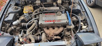
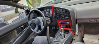
The reason the O2 sensor has 4 wires is because it's heated. If it's only the two heater wires that are damaged, and the two shielded wires going to the ECU are undamaged and correctly pinned, it should work. I had to repair mine as well.
 
Got the o2 sensor plug In & thr new coolant temp sensor installed. started the car and the car still shows a -47 with a timing at 61 before I started it. Once I started it and let it run for a few seconds and turned it off this is thr 2nd one where timing shows 5 and a coolant temp of -54. What else would be causing it to not read it correct . I will be getting the stock MAF tomorow and will see where that gets us.

Also when I pull the rear hatch lever I hear it pop in the back but won't release. Any thoughts?

20240811_095440.jpg


20240811_095510.jpg


20240811_100413.jpg


20240811_100630.jpg
 
Got the o2 sensor plug In & thr new coolant temp sensor installed. started the car and the car still shows a -47 with a timing at 61 before I started it. Once I started it and let it run for a few seconds and turned it off this is thr 2nd one where timing shows 5 and a coolant temp of -54. What else would be causing it to not read it correct .
Man I don't know but we should look at some basic stuff, like finding out what your firmware version is and your software version. If they are too much out of sync, sometimes it won't work. What I've read is that the software on your laptop can be newer than the firmware that is in the ecu, but it can't be older. I don't know if there is such a thing as firmware that is too old, but we should look.
For firmware version, I don't know how to get that from a log. The way I know is, you get a screen shot on your laptop with it connected to the car and the key is on and you are "Connected". Then the firmware ver and some other stuff is displayed in the lower right. So we need a screen shot - like this:

firmware version and boot version screen shot Dec 8, 2021.png


I'm suspecting that your firmware is really old because you said earlier that you don't find 3" GM MAF in your Base MAF Type drop down. Mine shows 3 different GM MAFs there. And my firmware is a few years old.
I didn't suggest doing a firmware update because you said that you tried putting the newest software onto your laptop and it wouldn't install. And that would be a problem! Because you don't want new firmware with old software! That I have read will not work! You gotta get new software install to work on your laptop before installing new firmware on the ecu, I think!


Ok now we need a screen shot of the software version. That you can get just by starting the app. You don't even need a log. Just start the app and pick Help, then pick About. Then you'll get this pop-up that shows the version number. Like mine here is 3.36.73 which is not the latest but it's pretty recent and it's working ok with my firmware 3.36.64.

ECMlink software version from Help, About.PNG
 
here is the firmware 3.46.226
Ok, that is actually the software version. They call it "the laptop application".
Anyway that is a good version, it's actually the latest version of the V3 software.
Here's the page where they list all the V3 software versions from newest to oldest.
Yours is right at the top (newest).
https://www.ecmtuning.com/wiki/v3changelog

We still need the firmware version.

Something is wrong I think because when I look at your logs, some features are missing.
Like I don't see any GM MAFs listed in Base MAF Type. There should be 3 listed there.
And in View, ECU Config, I don't see a tab for MAF Clamp. It should be right under MAF Comp in the upper left of the page.
Like this:
ECMlink tabs I have listed in View, ECU Config.PNG

There are a few other tabs I see in mine that I don't see in yours.
So, I don't know but maybe they aren't in your firmware.
It's odd because the V3 features for GM MAF and MAF Clamp go back all the way to 2009, maybe even earlier.

Aha, I think it will turn out you have V3Lite.
https://www.ecmtuning.com/wiki/prodcompare

Still, let's see the firmware version.
 
Last edited:
Could the plug in for the coolant tempnsensor be bad and that's why it's reading -50. Here is what the ecu looks like. I will get the MAF hooked up tonight and get a video of the car running with the firmware on the car. Also will check th4 plug in for the sensor.

Didn't even know they had a v3 lite. It should work for me shouldn't it? Just looked into it and with me not going above 8k or past 25psi lite works for me. For installation it is just plug the ecu back in so it is functioning properly. Hopefully the sensor has a lose wire on the pigtail. I'll unwrap it and look also. Before I do that I will plug the sensor into thr other coolant temp sensor and see if it reads that one above jt that goes to the a.c.

20231104_141726.jpg
 
Last edited:
That is a common problem with the hatch not opening. Stick something under the release lever to keep it up and then walk around and lift up the hatch. The springs wear out and keep it from opening all the way. Happens all the time, especially with the winged hatch.
 
Could the plug in for the coolant tempnsensor be bad and that's why it's reading -50. Here is what the ecu looks like. I will get the MAF hooked up tonight and get a video of the car running with the firmware on the car. Also will check th4 plug in for the sensor.

Didn't even know they had a v3 lite. It should work for me shouldn't it? Just looked into it and with me not going above 8k or past 25psi lite works for me. For installation it is just plug the ecu back in so it is functioning properly. Hopefully the sensor has a lose wire on the pigtail. I'll unwrap it and look also. Before I do that I will plug the sensor into thr other coolant temp sensor and see if it reads that one above jt that goes to the a.c.

Yes the coolant plug could be bad, or even at the other end where the 3 harness plugs plug into the ecu, a female connector in those plugs could be bad. Connectors in the engine bay are more likely to be bad because life is tough in there, and corrosion. But they can be bad at the ecu end too from bad handling. My 3 plugs at the ecu end of the harness had the release tabs broken off and I think there was one terminal there that was bad electrically, when I first got the car.

I've forgotten now if you have the diagram that shows the ecu pin locations for 1g? Probably do.
But see if this page works for you. It's keyword searchable and they show it organized 2 different ways which sometimes is handy. It's in the DSM VFAQs.
http://www.vfaq.com/mods/ecu-harness-1G.html

Then there's another diagram that shows the whole 1990 engine wiring harness. It's too many pixels to post here full size as a picture (it gets shrunk to the point you can hardly read it). So here's the original, on the Hotrod Coffee Shop web page:
1990 DSM 4g63 Wiring Diagram
They have a slightly different diagram for 1991-1994 DSM.

Yup, V3Lite should be OK for what you are doing, anything up to about 2,000 Hz on the stock 1g MAF.
If you have no cat and you have an aftermarket downpipe and 3" exhaust, and non-stock boost control, you can exceed 2,000 Hz pretty fast.
If that starts happening then you could easily upgrade to Full V3 for about $150 and it's just a different firmware that they sell you. Then with Full V3 you'd have MAF Clamp which would be one way to go if you want to push the stock 1g MAF a little further. That's why I was noticing that your rig at the moment doesn't have MAF Clamp. And you'd have boost control in the software too.

If you have a multimeter that can read ohms (resistance) check the resistance of your coolant temp sensor when it is just sitting there at room temp, or outdoor temp, whatever is easy. Then we could compare it to a chart.
 
Last edited:
We'd probably need a bigger pic of the ecu to get a good look at it.
Need a trick to do that.
The trick is understanding that the site reduces your pic to where the longest edge of it is only 2000 pixels. Even though it was probably a lot more than that coming out of your cam.

So take the pic with the cam in square format if you can, with just the ecu in the frame, no or little background.
If your cam doesn't have square format, use 4x3 or whatever is the closest thing you have to 1x1.
The pic you posted comes through as 901 x 2,000 pixels. The square area of it that contains just the ecu is only about 850 x 850 pixels. So the detail isn't good enough. Not enough resolution.

With a good pic, one of the guys in here that are good at spotting circuit board problems could probably tell if there's a problem. Like @steve , and a few other guys. I'm not the best at that.

You are probably shooting with a cell phone cam that has 2 or 3 lenses. Don't use the wide angle lens. Use the Mid or the Tele. Probably the Mid. Usually that's set for you by the zoom number and that works a little different with different phones. So I don't know exactly what to tell you for that but probably a somewhat "normal" zoom number or a little more, like 1.5 maybe.
 
Last edited:
Could the plug in for the coolant tempnsensor be bad and that's why it's reading -50. Here is what the ecu looks like. I will get the MAF hooked up tonight and get a video of the car running with the firmware on the car. Also will check th4 plug in for the sensor.

Yes the coolant plug could be bad, or even at the other end where the 3 harness plugs plug into the ecu, a female connector in those plugs could be bad. Connectors in the engine bay are more likely to be bad because life is tough in there, and corrosion. But they can be bad at the ecu end too from bad handling.
Definitely check the wiring at the connector and at least a few inches back upstream. Good call about trying the other sensor, too.

If neither turns up anything suspicious and you still have issues, check continuity of the wires from the engine bay connection to the ECU to rule out bad wire somewhere else along the harness.
 
got the maf on th4 car and it's idle at first was high but finally came down. Thr check e gine light did come back on which I am assuming is going to be from th3 coolant temp sensor. I did switch the plug onto another sensor and it still didn't work so yes. It will be something in the plug, wire, or ecu. Here is a video but it's long. on the 2nd video the idle did come down


20240814_160133.jpg
 
got the maf on th4 car and it's idle at first was high but finally came down. Thr check e gine light did come back on which I am assuming is going to be from th3 coolant temp sensor. I did switch the plug onto another sensor and it still didn't work so yes. It will be something in the plug, wire, or ecu. Here is a video but it's long. on the 2nd video the idle did come down
Hey good, I saw Airflow jump up to 20 gm/sec at 24 seconds in the video when you blipped the throttle. So it looks like the MAF is working.
You should display MAF too though. It will give a number in Hz.
Also, I'd change the Airflow units to lb/min which makes rule-of-thumb easier for most of us.

Yeah I see the O2 is still just reading 0.80 volts all the time so that's still messed up.
Display Battery.
Display ISCPosition.
Display MAF.
You might have to turn them on first in Edit, Captured Values, with the laptop connected to the car.
Idle Switch is working, that's good.

Firmware: 3.24.152
Yay now we know!
That dates to 2012 so it is pretty old, and it is V3Lite firmware.
I don't know that it's a problem though.

Here's the history of V3Lite firmware all listed out:
ECMLink (V3Lite) Firmware Changelog
 
Last edited:
I am not sure if i am uploading the log correctly. I did get one of the dtc warning off. The MAF sensor one is gone and now just the coolant temp sensor one. I did peel the wire back and found they were spliced back together so i cleaned it up with electronics cleaner and stripped new wire and spliced them back together to still not have it read. I will get the plug off and use just the wires to eliminate the plug itself being bad. The iscposition isn't available for me on mine.

The rear latch i did try that and still no avail. This latch stopped opening over 10 years ago when i had a crazy system in it. I will spray more wd40 in it and see if i cant get it to break loose. I don't think you can pull the plastics off to access the hatch assembly itself without getting the hatch open to remove the plastic piece around it LOL. If i am wrong please chime in. The car dose seem to not want to run when i first start it which is new LOL but settles itself out with some throttel maybe the ecu getting back adjusted to the new maf? Hope this log is loaded and you guys can take a view of it.
 

Attachments

I will get the plug off and use just the wires to eliminate the plug itself being bad.
Be really careful with that. Don't let the 2 wires from the ecu touch each other when the ignition is on - it might damage the ecu! They have a small voltage on them from the ecu and they aren't supposed to see zero resistance, like a short. That circuit is made to be attached to something that has thousands of ohms of resistance, or at least hundreds of ohms. Like the coolant temp sensor.
The 2 wires from the ecu should be a green with black stripe, and a yellow with green stripe.

I am not sure if i am uploading the log correctly. I did get one of the dtc warning off. The MAF sensor one is gone and now just the coolant temp sensor one. I did peel the wire back and found they were spliced back together so i cleaned it up with electronics cleaner and stripped new wire and spliced them back together to still not have it read.
The log is there, it works. When I pick it, it downloads to my Downloads folder in Windows.
Man it's so good to see the DTC gone for MAF!

I see 3 things that you should change on your Inputs page. Like this:
markup Inputs page smaller MAF Inputs page .JPG


Unlocking that one checkbox should make a little difference.
The other 2 things, I don't know if they will make a difference, but they should be undefined.

See if you can get Battery to show up in the logs. Lite should have that. I thought ISCPosition would be there too but not sure about it.
I did get MAF to show up and your MAF Hz were around 45 at that high "idle" of around 1,100 rpm. That's about right. Good!
 
Last edited:
Today when I get home and it gets cooled off I will go make those changes u recommend. I will be careful when doing that by putting tape on each one before i turn thr car on to eliminate them touching. I am assuming everything else on the log looks good.

I have the bearing for input shaft & the brake master cylinder to replace then I can actually drive the car!!! I need to bleed the clutch again a few more times to see if I can't get the clutch any more springy. Was hoping thay would fix the sensor. scares me with wiring tbh. especially with the ecu.
 
the display values and what I currently have on the display as of now
Sometimes the value you want to display is not in this list that you showed with your pic here.
When that happens you have to first assign it to be a Captured Value.
You do that in the list that you get by picking "Edit, Captured values" and you have to do that with the laptop hooked up to the ecu and the key on, so your ECMlink software is "Connected".
I show "Captured values" in the screen shot below.

In my screen shot you also see the "hover help" that comes up if you just hover over it for a couple seconds with the mouse. "Define which values each device will log". That's what it does.

After you pick what you want to add from this list, then go to the "Displayed values" list and look for those items and add them to be displayed.

So it's a 2 step process for any items that weren't already assigned to be Captured by default.
Capture.
Display.

Then make a quick test log just to be sure those items are really there. They should be displayed or at least they should be in the list of items you can pick from in Displayed values.

If you pick the "Captured values" item when your laptop is not connected to the ecu, you'll get a popup that says "Port refused to accept ....."
No harm done, it's just telling you that you aren't Connected.
You gotta be Connected.

ECMLink - hovering over Captured Values, and the hover help that comes up.jpg
 
scares me with wiring tbh. especially with the ecu.
Yeah the 2 electrical lugs on the ECT sensor are so close together.
Here's a way you could do it pretty safe, just for temporary probably.
You could crimp quarter inch wide female quick connects onto the ends of the 2 wires.
The lugs on the ECT sensor believe it or not are a standard quarter inch wide, so the quarter inch standard generic female quick connects will fit right on them.
Then after getting them on I'd still separate them with some electrical tape or heat shrink tube.
Because these standard quick connects are a little bit "fat". They are not all slim and trim like the specialized automotive terminals are.

Here's a pic I just shot of my spare ECT sensor with 2 female quick connects and the bag that the quick connects came in. You can buy generic connectors like this locally.

I've been thinking about if it would actually hurt the ecu if you accidentally touched the 2 wires together with the key on. I really don't think it would because there is an internal resistor inside the ecu as part of this circuit. But I'm not sure. I'd just really try to avoid it. I think this circuit in the ecu works a lot like how an Ohm meter circuit works. And you can touch the probes of an ohm meter together and it doesn't hurt anything. It just tells you "0 ohms" which is the right answer 😂
Maybe @19Eclipse90 or @steve would know.

20240815_154110  quarter inch female quick connectors and a 1g DSM ECT (temp) sensor .jpg
 
Last edited:
Definitely still going to be carful! Not able to do it today. was jusy to busy but will get it done tomorrow. So if it still doesn't read once I wire it directly without the plug. what would be the next solution? check the ecu plug in and look for a wire that's pulled out? I don't have anything to check for a broke wire
 
So if it still doesn't read once I wire it directly without the plug. what would be the next solution? check the ecu plug in and look for a wire that's pulled out? I don't have anything to check for a broke wire
Yes I think checking those 2 wires is the next thing.
The easiest and best way to do that is with a multimeter.
So you need a multimeter if you don't already have one.
With a multimeter you can also check the sensor itself but the sensor is not going to be the problem, I mean the new one and the old one both didn't work. So checking the sensor would be more of a self-test to see if you are using the ohm scale on the multimeter properly. Something that should be done of course!

But the 2 wires -
With them both disconnected from the sensor and the Key turned ON:
1.) The yellow with green stripe wire should have about 4.7 volts on it with the key turned on. You'd check that with the meter set to read Volts DC. Touch the red (+) probe of the meter to the end of the wire, and the black (-) probe of the meter touching any convenient grounded bare metal in the engine bay. Meter should say about 4.7 volts.

2.) Then move the black probe of the meter to the other wire (the green with black stripe wire) and again the meter should say about 4.7 volts.
At this point you've really tested both wires, and their connection to the ecu, and their continuity from one end to the other.
In step (2) above, if you think there's a chance that you would accidentally touch the meter probes to each other while they are touching the wires, then don't do step (2). Do step (3) instead (below), which is another way to check the green with black stripe wire. I'd do step 3 whether you do step 2 or not.

3.) The green with black stripe wire should be a ground. A sensor ground. You can check that with the multimeter set to ohms (resistance) and put one probe to the end of the wire and the other probe to any convenient grounded bare metal that is nearby in the engine bay. The meter should say 0 ohms. If there is a break in that wire, or if it isn't connecting to the ecu, the meter will read a very high number like some M ohms (millions of ohms) or it might say OL (out of range) or something similar.

Note that test (1) above is also a partial test of the ecu, because the 4.7 volts is coming from the ecu.

Testing the sensor:
This is easy with your multimeter set to read ohms again.
With the key OFF and the 2 wires disconnected from the sensor:
Put the 2 meter probes to the 2 electrical lugs coming out of the sensor.
Meter should read about 2,400 ohms at 68 deg F haha good luck finding that there right now!
At 100 degrees F I think the resistance is about 1,700 ohms but there is a typo right there in my copy of the FSM! At 176 degrees F it should be about 300 ohms.
Don' touch the meter probes to a battery or to any voltage source when the meter is set to read Ohms!
 
Last edited:
Add Value - Be Respectful - No Trolling - No Misinformation - Participate Often!
Support Vendors who Support the DSM Community

Build Thread Updates

Latest Classifieds

Back
Top