
bjones18
15+ Year Contributor
- 299
- 33
- Jun 3, 2004
-
canton,
Michigan
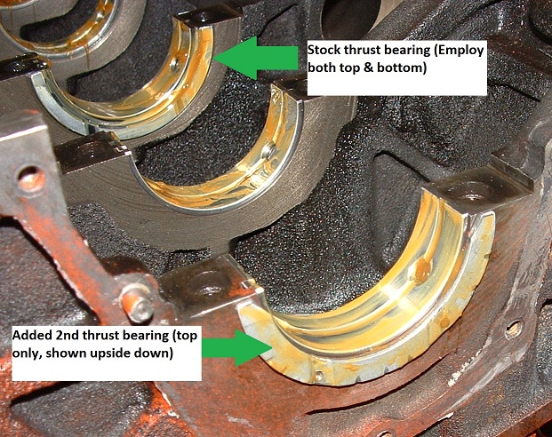
I've written a few threads about crankwalk over the past few years, but now have posted a fix for 7 bolt engines. It is relatively simple and very low cost
Tech article:
http://www.dsmtuners.com/forums/articles-engine-fuel/453033-crankwalk-fix-7bolt-others.html
Tech article:
http://www.dsmtuners.com/forums/articles-engine-fuel/453033-crankwalk-fix-7bolt-others.html


