The Top DSM Community on the Web

For 1990-1999 Mitsubishi Eclipse, Eagle Talon, Plymouth Laser, and Galant VR-4 Owners. Log in to remove most ads.

Please Support Kiggly Racing
Please Support Morrison Fabrication

2G Not starting

This site may earn a commission from merchant
affiliate links, including eBay, Amazon, and others.

This site may earn a commission from merchant affiliate links, including eBay, Amazon, and others.

So there is supposed to be constant power with key on eh.

What grounds am I going for from the ECU and yes the board is fine by me eyes. The sensor ground is not broken confirmed by continuity test.
 
Have them printed but I haven't really had help over there other than Dave mentioning it prob isn't a hardware issue.

Also pin 13 & 26,that is to any ground metal for testing correct? Pin 88 would be which wire on the CAS plug that I use for a 1g CAS?
 
I need info asap.

I tested the 2 ground wires to any metal and nothing. I believe I found the mounting lug as well which is behind the passenger center console panel behind the radio and under the wire loom. There are 4 black wires that go there. I assume 2 are the 2 ecu pins, what are the other 2 wires going to?

It seems that the 2 ecu wires go up the harness and into the bay and then 4 come back in?
 
3 are standard ECU wire sized and the 4th is just a little bigger. I'm unsure of gauge size to be honest.
 
5 wires in the bay off the harness (section after firewall split) without a ground connection. 3 solid black with silver dashes (like the ecu ground wires), 1 black with a white stripe and the silver dashes, 1 black with a blue stripe silver dashes.


Black and Blue goes to the PTU. Black and white goes to coolant sensor, 1 solid black goes to MAF connection I don't use anymore, the other black goes to the TPS, and the last black goes behind the motor somewhere.
 
Have them printed but I haven't really had help over there other than Dave mentioning it prob isn't a hardware issue.

Also pin 13 & 26,that is to any ground metal for testing correct? Pin 88 would be which wire on the CAS plug that I use for a 1g CAS?

Pin 88 would go to the white wire on the 1G CAS.

I need info asap.

I tested the 2 ground wires to any metal and nothing. I believe I found the mounting lug as well which is behind the passenger center console panel behind the radio and under the wire loom. There are 4 black wires that go there. I assume 2 are the 2 ecu pins, what are the other 2 wires going to?

It seems that the 2 ecu wires go up the harness and into the bay and then 4 come back in?
...
3 are standard ECU wire sized and the 4th is just a little bigger. I'm unsure of gauge size to be honest.

You're talking about the ground location in the cab, correct? Assuming the '97 is similar enough, per the '98 FSM: CPS (standard size wire); O2 Sensor (standard); ECU pins 13 and 26 and the CAS combine into one (larger wire); and the knock sensor (standard).

5 wires in the bay off the harness (section after firewall split) without a ground connection. 3 solid black with silver dashes (like the ecu ground wires), 1 black with a white stripe and the silver dashes, 1 black with a blue stripe silver dashes.

Black and Blue goes to the PTU. Black and white goes to coolant sensor, 1 solid black goes to MAF connection I don't use anymore, the other black goes to the TPS, and the last black goes behind the motor somewhere.

Not sure what to make of this bit. Can you explain a little more what you're referring to or trying to track down? No idea if it helps at all, but in relation to the two black wires you've listed (to TPS and to MAF), the diagram shows black wires running to the two oxygen sensors, coolant temp sensor, and MDP sensor.

Maybe that will get something going in here for you.
 
The 4 wires in the cab ground point go to a single bokt via a ring terminal. I have no ground at the ECU ground pins to the body. That's why I'm chasing down where they all go.

Of the 4 relevant ground wires off the harness I tested which is mentioned above with its component, I'm unsure if the are switched grounds or constant grounds. Every other black wire in the harness I tested, tested positive for continuity to the body. Only 5 wires did not, and I do not use the MAF ug any more.

All of this is to figure out why I'm not getting a pulse to the injectors which is at the least, the CAS not receiving a switched power signal. This led me to find that the ecu is not grounded.
 
Here is what I came up with from the wiring schematics from ECMLink and its a '96

ECU pins 13 & 26 are grounds for the crank and cam sensor.

The black wires that had no ground are along this route.

MAF connects to the TPS, front o2, rear o2, coolant temp sensor, and the MDP. that wire is not a ground wire.

What appears to be the ground point in question grounds the crank sensor, knock sensor, VSS, and the tach.

So it looks like I need to test the cam/crank ground wire at tge sensor plugs.
 
Last edited:
your tracking down all of this because you think you fried something when you hooked up the battery backwards? I think your taking this a little to far here... I have done this before on a 1G and all that happened was the 100A fuse blew in the fuse panel.

from what I have gathered you just did a rebuild and it ran before right? I would check basic things that it could be first

1 - You had spark plug wires off... are they back on in the correct firing order? you mentioned that they were but are you aware of the order? 4-1-2-3 number one being the timing belt side... did you re-locate the coil pack while you had the car apart? because if you mount it in a backwards fashion IE. on the fender, than you have to remember that its now opposite of what it should be.

2. was the C.A.S. installed in in the proper direction? ... because you have had it out now

3. check your compression... is it equal in all cylinders? if it is high on one end and tapers off to lower on the other end than your cam timing isn't set properly. it should*** still at least run if the cam timing is out however.

also if your injectors are firing once every time you cycle the key try cycling it a couple times than crank it to see if it starts for a second or two. that will verify that your spark system is operating as it should be.

bottom line is I don't think you would have shorted something by putting on the battery backwards... think of what you did when you had the car apart that may be causing it not to run now

"put on a different injector resistor pack" try putting your old one back on as-well.
 
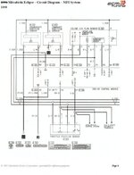
What difference it will make, I don't know. Here's what the '98 diagram looks like, more or less.
 

Attachments

  • MFI_page 6.jpg
    MFI_page 6.jpg
    45.6 KB · Views: 186
Brian, where was that located at on ECMLink? It's defiantly different, even with just the grounding pints listed.

Jaden, please re read. You would notice I had to replace the fuse and ECU already due to being fried. No injector pulse, no switched power to CAS. everything you listed is already finrbon the motor. I never said they were firing once every time. Ivmerely noted that there was a quick blip on the light which could have been from the initial key turn. There is NO pulse period.
 
Probably should have noted that I used/modified the ECMLink diagram to match what my '98 FSM hard copy shows (save me the trouble of scanning it in). Everything else, as far as I noticed, is pretty much the same. Again, not sure if it matters at all, but figured I could try to help. :)
 
Do you have the rest? I need the grounding points and and linking pages.
 
so to sum that up than you have no power to your CAS and your injectors are not getting ground?

I wonder if it would start up if you ran a power wire from a good source to the connector side of the CAS.
it wouldn't be a permanent solution obviously but it would narrow down your problem
 
...this thread is handy. I am having the EXACT same problem. I accidently shorted the battery and am tracing down the exact same symptoms. All of my grounds tested out. As for the CAS, maybe this will help some. I tested the blue red wire with the key on and got about 4.5 V fairly steady. The diagram also says 5v at the 88 and 89 pins, so I don't think you should be getting 8 or 9v on the signal wire. Probly not the main issue, but I have been tracing the same circuit all day also. I really hope you get this figured out because you may be saving me in the process.
 
When I tested the CAS wires for voltage, I didn't get any on the wires with the key turned. I didn't text them together, just a single pin to a ground.

Hopefully I can get to testing tomorrow, I've been very busy lately and the car is in another location from the house.
 
Grounding Locations
http://i100.photobucket.com/albums/m17/19Eclipse90/1998%20Turbo%20Wiring%20Diagrams/70_5_GroundLocations.jpg
http://i100.photobucket.com/albums/m17/19Eclipse90/1998%20Turbo%20Wiring%20Diagrams/70_6_GroundingLocations1.jpg
http://i100.photobucket.com/albums/m17/19Eclipse90/1998%20Turbo%20Wiring%20Diagrams/70_7_GroundLocation2.jpg

Power Distribution
http://i100.photobucket.com/albums/m17/19Eclipse90/1998%20Turbo%20Wiring%20Diagrams/90_30.jpg
http://i100.photobucket.com/albums/m17/19Eclipse90/1998%20Turbo%20Wiring%20Diagrams/90_31.jpg
http://i100.photobucket.com/albums/m17/19Eclipse90/1998%20Turbo%20Wiring%20Diagrams/90_32.jpg
http://i100.photobucket.com/albums/m17/19Eclipse90/1998%20Turbo%20Wiring%20Diagrams/90_33.jpg
http://i100.photobucket.com/albums/m17/19Eclipse90/1998%20Turbo%20Wiring%20Diagrams/90_34.jpg
http://i100.photobucket.com/albums/m17/19Eclipse90/1998%20Turbo%20Wiring%20Diagrams/90_35.jpg

MPI Circuit
http://i100.photobucket.com/albums/m17/19Eclipse90/1998%20Turbo%20Wiring%20Diagrams/90_68.jpg
http://i100.photobucket.com/albums/m17/19Eclipse90/1998%20Turbo%20Wiring%20Diagrams/90_69.jpg
http://i100.photobucket.com/albums/m17/19Eclipse90/1998%20Turbo%20Wiring%20Diagrams/90_70.jpg
http://i100.photobucket.com/albums/m17/19Eclipse90/1998%20Turbo%20Wiring%20Diagrams/90_71.jpg
http://i100.photobucket.com/albums/m17/19Eclipse90/1998%20Turbo%20Wiring%20Diagrams/90_72.jpg
http://i100.photobucket.com/albums/m17/19Eclipse90/1998%20Turbo%20Wiring%20Diagrams/90_73.jpg
http://i100.photobucket.com/albums/m17/19Eclipse90/1998%20Turbo%20Wiring%20Diagrams/90_74.jpg
http://i100.photobucket.com/albums/m17/19Eclipse90/1998%20Turbo%20Wiring%20Diagrams/90-75.jpg
 
Last edited by a moderator:
Well, after reviewing everything that Brian posed and if I remember correctly which wires I tested that came back negative for ground, I'm looking at some fried wires.

Pin 13 and 26 have no continuity and both are grounded at ground locations #10 and #3. However, the cam position sensor is directly grounded to #10 but pin 13 (ground) is attached to the ground wire off the crankshaft position sensor. That wire travels to ground #10 but pin 26 (ground) is attached to the #10 ground wire AND goes directly to ground #3.

Having a 1g CAS, that leaves me with 1 #10 ground wire to work with and that's coming off of the crank sensor plug.

I'm not positive off hand, but I believe that my PTU did not have a ground connection and that is grounded directly to #3 as well.


The other 2 wires that are on ground #2 are both o2 sensor wires spliced into a single wire and the knock sensor. Both of which are un used.

The vehicle speed sensor and the knock sensor again are also grounded at #3. So I'll likely need to check proper operation of the speed sensor and knock sensor to make sure they didn't fry.

2 grounds locations and 6 wires to go through. 2 of those devices would cause a no start issue as well.


Now that the info is there, would not having ground to the CAS cause it to not pulse the injectors but it will spark the plugs?


I'm still a noob in some areas :p
 
Both the CAS signal and crank signal are needed to tell the ECU which injectors to fire.

The crank sensor alone tells the ECU which waste-spark coil has it's pistons approaching TDC.

Plenty of 2G guys (who still use their crank sensor) have had a no-start condition from a bad CAS while still having good spark.
 
That would be me. Good spark, no start... but plenty of gas pouring out of 2 injectors when it's cranked...

As for the ground in the CAS, I know that in my 95 CAS (which i hate more than cancer), not having a ground would prevent the switch from operating and therefore would not send any sort of signal to the ECU. It'd be a flat voltage. It's supposed to spike with the Hall ring tabs passing through it. I'm not sure, but I think the CAS sensors that are mounted on the left side of the camshaft (where they all SHOULD'VE been placed... stupid 95 cas...) are optical sensors. I assume there's a photoelectric sensor in it that would vary the voltage in a simlar fashion to my magnetic sensor. Being that there's a switching of voltage occuring, and voltage passing through the circuit and not terminating at it, there would have to be a ground somewhere. If your CAS isn't showing continuity to ground, i would suspect it first.

As a side note, if you're running a 1g CAS, have your 2g CPS in place, and are getting spark but NOT getting any injector response... something is goofed up there also. The 1g CAS should be providing BOTH signals for the injectors and the sparks, to my understanding. That would suggest to me that the CPS and 1g CAS may be sending signal to the ecu, unless the 1g CAS was never spliced into the CPS circuit... then I really don't know exactly how that'd work. I would guess it would just function as a normal CAS would in a 2g OEM configuration, but I have no experience or basis for that assumption.

I believe I figured out what happened in my case also... the ecu is messed up. Almost all of the circuits tested within range, except they all were edging on the high side of the voltage norms. The crank position sensor circuit though has 8-9v running through it. It's a 5v circuit according to the schematic, so something regulating the current isn't working anymore. It's a real disappointment too. It's an EPROM 95 ecu that came stock with this car and has never been touched until I had to open it up. The screws were still sealed with the little alignment dot from the factory still present. It was one of the major reasons i bought the car, and now it may be broken beyond my ability to repair it. :cry: I'll probably have it repaired in the near future (if it isn't overvolted and ruined). For now, I just bought a 96 GSX non-EPROM ecu known to be functional. They are cheap and easy to find since they tend to get swapped for either EPROM's or 98-99 flashable ecu's. I don't have a turbo big enough to push past the stock map and I have an SAFC2, so no big deal.
 
Last edited:
Just FYI H@xt, the green top 1G CAS is an optical sensor but all others are hall effect.

Does that mean that the other 1g CAS's have a hall ring with 4 tabs on it? Or are the tabs duration calibrated to injector--->spark gap?? And how would that signal then be sent via 1 signal wire???

:confused:

Now I'm confused as to how they provide both injector and spark signals to a 2g... I know the circuit is spliced for the 2g ecu, since those signals are separate in the 2g pin harness.


LiquidX, I just re-read this to see if I missed anything important from anyone else and remembered you saying that you also got 8-9v on a signal wire... the schematic I have says CAS/CPS circuits are both 5v. That output isn't augmented by any additional connections between the sensor harness and the ECU, so that voltage should be being regulated at the ECU. If you have access to yet another functional ecu (unlike me) and are 100% sure you've got the wiring right with all the proper grounds in place, you may want to make sure you don't have a 2nd dutch oven under the dash. I hope that isn't the case, but it's pretty common to have a wiring issue fry a computer (even if only manifest by shorting the battery), only to be "fixed" and fry another. Wanna know how I know that? -- my Jeep --->:tease: WTF<--- Me -- ... it's an expensive lesson to learn. :ohdamn:

Just to be sure, could one of you with a fuctional ECU please check your "ON" voltage and "Start" voltage range on pin 89 (95-96 ECU)? That is the CPS pin and is shown as a 5v circuit. I find it kind of strange that both of us would be seeing the same voltage there with these sort of electrical problems. It is basically the same sensor as the CAS, and I get 4.5v on it, so I think there is a problem. It would suck to find out that is what it is SUPPOSED to be at, regardless of the schematic.
 
Last edited by a moderator:
Support Vendors who Support the DSM Community
Boosted Fabrication ECM Tuning ExtremePSI Fuel Injector Clinic Innovation Products Jacks Transmissions JNZ Tuning Kiggly Racing Morrison Fabrications MyMitsubishiStore.com RixRacing RockAuto RTM Racing STM Tuned

Latest posts

Build Thread Updates

Vendor Updates

Latest Classifieds

Back
Top