yeti-gvr4
10+ Year Contributor
- 422
- 2
- Dec 23, 2010
-
san diego,
California
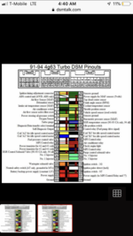
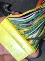
So I looked up a 1g ecu pinout with colors ( attached ) and a good amount of my wires are different colors or lacking pins/stripes.
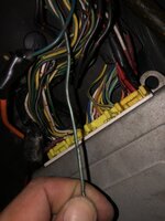
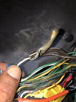
On another note there’s a - green wire/white pin stripe / red dash -
WIRE just hanging not connected to ecu at all, the pin out says this should be my idle switch or tps sensor, two things that would cause my idle to surge.
So I checked the pin location and there are wires there still plugged in, also a different color that indicates on the pin out.
But the idle switch and tps sensor wires have been molested, still seem to be connected and working ( visual )
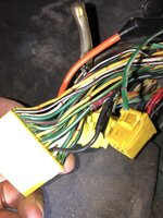
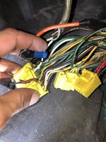
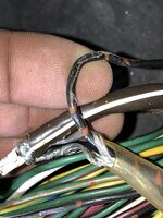
Last but not least my knock sensor is consisting of 3 different wires being spliced into one ecu pin. TWO large brown With white pin stripe , and one small black with red dashs wire. ALL going into the original stock white knock sensor wire.
What to do? Where to start?
How can I check if my knock sensor is working properly? ( I have it set to boost gauge on Link and it flashed every now and then on my shitty tune )
How can I check if my tps or idle switch are working properly? The guy who tuned my car was mentioning the isc or tps something was not responding to adjustments on Dsm link.
My bad for all the questions is such a short amount of time, any help is greatly appreciated , also attached is the ecu pin out I followed
Attachments
-
 B624C0FF-B216-4C93-ABCC-1C0EFF3B6459.jpeg836.6 KB · Views: 111
 -
 739B9683-E6E6-4F8A-8A42-DDFF6D540F7F.png187.5 KB · Views: 128
 -
 C88405A9-1134-43C1-BF58-C5DF33B7A499.jpeg757.7 KB · Views: 68
 -
 2B750934-0ECC-4397-9213-6A15F0E2061E.jpeg939.8 KB · Views: 64
 -
 0C534E98-E4AB-4303-A57C-06DC344CA30A.jpeg671.4 KB · Views: 82
 -
 E98A2EA9-7703-40AD-B8A4-5975739C3659.jpeg843.9 KB · Views: 44
 -
 28600225-7CB9-408B-9443-FE4900DD632B.jpeg688.7 KB · Views: 51


