The Central Hub for DSM Community and Information

For 1990-1999 Mitsubishi Eclipse, Eagle Talon, Plymouth Laser, and Galant VR-4 Owners. This is where the DSM platform history is documented and archived. Log in to help us in our mission, and to remove most ads from the browsing experience.

phpkpdab8am.jpg

greengoblin's AWD Project

This site may earn a commission from merchant affiliate links, including eBay, Amazon, and others.

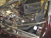
I cant wait to see the finished product. Why did you buy one sparco evo seat and one pro2000 seat? do you recommend one over the other? Around how much do you think they weigh?

Here are all the specs on the Sparco seats.

http://www.sparcousa.com/resourceFiles/26.pdf

I chose to put a evo seat on the passenger side because it is bigger and will fit more people into it if I want to take them for a ride.

As for what is best. I would say it's the seat that fits you dimension wise would be the best. For me the pro 2000 fit well.

Kevin
 
09-29-2009 to 10-10-2009
My dampners came in form Robispec! Also the Koni upper hats DG recommends mate up perfect with the K&W springs if you use the 2.5 inch adaptor they offer. Now I just need to build the standoff's per DG specs and I can put these togther. :bounce Yeah!


suspension008.jpg


suspension.jpg


Changed up the spring color.

Before:
KWcoated3.jpg


AFTER: :beerchug
KWcoated.jpg


Now have to decided what color I want the top hats to be. Polished Alum, Black or HKS/KW/candy purple to match the collars. HHHMMMMMM

Top hat with the bearings and studs installed . Oh, and I shot them in HKS/kw purple.(candy violet). They came out pretty damn close to the factory anodized color. The ring in the back is in the factory finish. Good enough for me:5band

realcoatings054.jpg


Bling!

kW001.jpg
 
Last edited:
This is a great build. Goes without saying, but I love the innovation Kevin. :thumb:

thanks Sir!

In what way is the Evo seat bigger than the Pro2000? By the measurements, it looks like it's smaller in almost every way.

I should have been more specific. My other seat is an EVO 2. Sorry, I just figured that the person who asked had seen the pic and knew.

Kevin
 
02-05-2010 to 02-28-2010

Popped out one of the front cross member bushings to start drawing up the plans. What's interesting about this unit is that it does not have a steel outer sleeve like every other bushing I have pressed out so far. It made getting it out a lot easier. Not much of an update but it's something right?

frontxmember011.jpg


My front cross member bushing came in .

Big thanks to Adam( black_gst) for producing these.

My drive shaft bushings showed up too.

Should install the front x- member bushings this weekend.

Drive shaft bushings
Driveshaftbusings.jpg


Prototype front X-member bushings.
frontxmemberbraces002.jpg

frontXmemberbushingsmetal.jpg

frontXmemberbushingsmetal2.jpg

frontXmemberbushingsmetal3.jpg


Proto-type bushings installed! Everything went smooth. Perfect fit and finish.
Things to note if you get a set from Adam.
I can't see doing this with out a press.

Most the holes that theses press into have weld splatter on the walls. They are going to want to make sure they clean that off. I used a dremel and a small flapper wheel. It worked great.

Put the outside lower top spacer on after you hang the X-member off the studs. Since your using a bolt in that location it's easier.


On to the pics
crossmemberbusingsinstaled5.jpg

crossmemberbusingsinstaled4.jpg

crossmemberbusingsinstaled.jpg

crossmemberbusingsinstaled3.jpg

crossmemberbusingsinstaled2.jpg
 
11-06-2009 to 04-18-2010


Rear suspension lower arms build progression:

This took a while so I tried to put it all in one post to give a clear view of the progression. Enjoy


Here is a peek at what the toe arm will sort of look like. I'm going to be using a rod end and adjustable tie Rod adapter instead of the tie rod end in the picture but you get the idea.:fry

toearm006.jpg


toearm005.jpg


Getting close to having the toe arms complete. Just need to ream the hole in the knuckle to fit the larger pin that I'm using. Then I'm going to tackle the trailing arm and last the lateral arm. It going slow but moving. I'm hoping to get my upper arm cone spacers back soon. The machinist made an error so they where just a hair to wide for the clevis. Easy fix really but it's still a pain.

OEM Toe arm
toearm001.jpg


Toe arm 2.0
toearm20001.jpg


One rear trailing arm down! See i do still work on my car. Big thanks to my friend Jake for advice and doing the TIG welding for me.

Next the lower lateral arm.


rearsuspensionarms.jpg

rearsuspensionarms002.jpg

rearsuspensionarms003.jpg


A bit closer. Rear hubs should be here soon. Then I can slap the axles in and adjust the rear arms a bit more and make sure there is know binding. Attach the sway bar mounts to the lateral arms. Then mod the say bar a bit so it can be adjustable. Bam the rear suspension will be do! It might take a while. LOL 
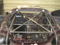
Still progress is progress.


rearsuspensionalmostdone003.jpg
 
07-24-2010 to 07-25-2010

So here is what I have done. I have been working on stuffing my car with metal bearings. The last arm do to is the compression arm. I saved this arm for last for many reasons. It controls are dynamic camber and toe on the front of the car under braking and acceleration. The bushing in it is huge and has a dog bone through the center for mounting it. Also the mounting bolts bolts are in single shear and that could be very bad with the change in peak loads it will see.

Just in case I went ahead and welded a tabs on the sides to put the compression arm bolts in double shear. A plate that will tie into several of the other bolts on the cross member to put those bolts in double shear. The cross member should be coated very soon. I also beefed up the lateral arm clevis so that it should not have problems with the metal bearing being used there. I actually did these welds myself so they could look better but hey, It's only my third time welding. Yeah!


Again not much but hey it's something.

bracing001.jpg

bracing002.jpg


Bam! Front x-member done!

60% SD gloss black. It is a bit washed out looking from the flash but you get the idea. It was still 350+ degrees so I didn't really want to touch it. Hurray for the ghetto oven. :) Also I know the garage is a mess too.


bracing009.jpg


bracing012.jpg


bracing011.jpg


bracing010.jpg
 
07-31-2010 to 09-27-2010

Front knuckle have been shaved and coated. It dropped right at 1/2 lbs per knuckle. More could be had but I stuck to the large easy to reach areas . I'm happy


frontknuckleshaved002.jpg


frontknuckleshaved006.jpg


Managed to rebuild my rack this weekend. We will see how it works. It as been rebuilt in the past I think. I found a sleeve in the bore behind the backup washer that is no where in the services manual. That and the extra set of ping marks on the bottom cover nut/cup seem to be a dead giveaway .
rackrebuild002.jpg

rackrebuild003.jpg
 
Last edited:
10-02-2010 to 03-08-2011

Stitch weld progression. This too a long time to do. so I grouped it all here:

A few pics of some of the stitch welding progress. It's slow going but at least I'm working on it. This is my fifth or sixth time welding, first time on thin metal that is impossible to truly get welding clean and upside down. So yes, it's not that pretty. I am picking it up pretty quickly I think :) I'm mainly going to work on the underside. I really want to get this car back on the ground by Jan. 1. Then I'll start working on the inside.

stitschwelding007.jpg


stitschwelding008.jpg


stitch005.jpg


I have almost all the under side over head stitch welding done.Need to fix a few spots and finish up a few little areas. Then on to the wheel wells.dancenana

stitchweldingmore002.jpg

stitchweldingmore001.jpg

stitchweldingmore003.jpg


I'm 99% done with stitch up the wheel wells on one side of the car. not the prettiest but it will work.

Snapped a few pics.

stitchweldingwheelwells003.jpg

stitchweldingwheelwells005.jpg

stitchweldingwheelwells002.jpg


Thought I'd make on last post on my thread for 2010.
Not to exciting but here they are. Just some more of stitch welding.
morestitchwelding001.jpg

morestitchwelding002.jpg

morestitchwelding003.jpg

morestitchwelding006.jpg


What are you looking at? 111 stitch welds is what it took around the inside of 1 door. I'm so glad they have baby monitors. If I didn't have that I would not be able to do anything to the car while my son naps. Slowly but surely.


111welds001.jpg

111welds004.jpg


Here are a few pics from a late night work session.

Note Zack scratching his head wondering what the hell am I doing here:and me in my sexy welding clothes.


carsnowdarrensvc002.jpg

carsnowdarrensvc004.jpg

carsnowdarrensvc005.jpg
 
10-15-2010 to 11-19-2010


Picked up the final pieces for my rear cross member. Yeah! Now I just need to weld the tab on and I can coat the cross member and be DONE with it!


VCstuff007.jpg


Had some time to do a little work on my car! welded in the extra mount for my rear diff.
Not much but hey I'm moving forward. I can coat my rear cross-member now!


Pumpkin028.jpg

Pumpkin030.jpg

Pumpkin035.jpg

Pumpkin037.jpg


I went back and did a better job on the welds (practice makes perfect) and added a gusset that I felt was really need. Let me say the gusset really made a big difference. This mount is not going anywhere.

halloween2010023.jpg


Rear crossmember done.
rearcrossmembercoated007.jpg
 
This brought me :

TheKIT001.jpg


THIS!!!!!!!!!!!!!!!!!!!!!!!!!! I'm one of what looks to be only a few to ever made. BUWHAHAH!!!!!!!:haha

TheKIT002.jpg

TheKIT003.jpg

TheKIT004.jpg

TheKIT005.jpg


Super big thanks to Fes of FXMD out of Vegas. He had to share his bed in his truck(Semi) with my body kit for several days. :borat You Sir are a rock star!!!!!!!!!!!!
 
Last edited:
04-27-2010 to 05-23-2011

Rear sway bar build from start to finish. Well almost. I still to this date need to fab up drop links. Those will be soon.


This is where I'm think about mount the cutom sway bar.

Excuse the crappy paint drawing but it's all I have to work with at the moment. Purple= bar Yellow= heim joints

Since my spare tire well is gone I was thinking this would be the best place to mount the bar. It would also be mounted to a much more ridged area than the cross member location.

It would be a unit like these. Not sure which one. One is WAY spendy.

Speedway Engineering Hollow Race Car Sway Bars

HRPWorld.com - Everything You Need To Build & Maintain Your Race Car.

Thoughts?


swaybarsetup.jpg


Rear sway bars came in today. Guy sent me the wrong arms though. I still will be able to start the initial mounting etc. I'm keeping my fingers crossed this works out like I think.....

Also did a buch more stitch welding.

swayrear002.jpg


I'll be making a jig for the fender braces just in case someone wants a set.

Kevin

Measure, measure, measure. Mark, punch,remove old brake line mounts, then drill big holes through frame rail. Should have some good updates in the next few days.


Kevin


swaybarhole002.jpg

swaybarhole001.jpg


Are you going to send a letter to Mitsu and say, "I re-engineered all your shits better, suck it!" Because I would. :fyeah

Funny stuff and thanks!

Update for you guys and more to come soon!

Sway bar will be pivoting on bearings not bushings. Take a look.

The tube will be welded in place. the needle bearings are held in place by a step/shoulder on in the tube and a set screw. The arms keep also hold them in place and they are riding on torrington bearings.
This thing moves so smoothly.

I need to get some end links but I should have the bulk of the work finished up this weekend if all goes well.


swaybarmountsandbearings001.jpg

swaybarmountsandbearings004.jpg

swaybarmountsandbearings005.jpg

swaybarmountsandbearings010.jpg

swaybarmountsandbearings009.jpg

Bar mounts installed. Rod ends for endlinks are ordered. Rear suspension is now DONE!!!!!!!!!!!!!!!!!!!!!!!!!!!! :fyeah THAT ONLY TOOK FOREVER.
Now I have to take it apart for paint.

swaybarmountsandbearings011.jpg

swaybarmountsandbearings021.jpg

swaybarmountsandbearings013.jpg
 
Last edited by a moderator:
06-21-2011 to 06-27-2011

There where a few who wanted to see what the compression bearings and such looked liked unassembled. Here is a pic that I had before install.

compressionarminsideview.jpg


Sorry for the bad pics. I think the lens need to be cleaned.
The dog bone has now been conquered. That concludes the bearings in the front suspension.


dogbone001.jpg


dogbone002.jpg
 
Last edited:
07-25-2011 to 07-30-2011


Mocking up the brakes so I can figure out the routing and build the lines. I am also going to start the front sway bar build. More to come soon.
A few pics not showing much, but I like pictures. :)


mockupswaybar001.jpg


mockupswaybar002.jpg


Stock EVO wheels, my ugly fat fenders laugh at your skinny asses.

Big thanks to Zack for letting me borrow the wheels.

Bringing the car down in the next few days to do more mock up work.


evowheels003.jpg


evowheels001.jpg


I wish I had this much time/patience to put into a car.

Thanks. I don't have much time. That's why it is taking so damn long. I guess I'm long on patience though.

I hate you because I'm so jealous...

You made me LOL .


DOWN!!!!!!!!!!!!!!!!!!!!!!!!!!!!!!!!!!!!!!!!!!! :borat

DOWN001.jpg

DOWN004.jpg

DOWN003.jpg
 
Last edited:
09-23-2011 to 10-11-2011

Full kit fitting is under way. This post will bring this thread up to date with where my build currently sits.

Let talk dzus clips shall we. If your going to use them the only one I feel are worth a damn use a hex drive to tighten them. The ones that use a blade/flathead style drive are hard to engage and are begging you to slip off and scratch your car. This pic shows the basic make up of a quarter turn faster to give you and idea how the work.


Duzusclips020.jpg


Now that you know what the fasteners look like let move on to the install some.
First I aligned my fenders. This takes some time and even more if you are using aftermarket fender that don't have predrilled holes. Self tapping screws work great for this.
Next I drilled a 1/8" hole where I want my buttons to be. Then I installed my cleco claps to hold the fender in place and removed the self tapping screws. The cleco are so nice when you need to remove and reinstall thing several times and hold the panels very well. I love them.

Here are some good pics of how the clecos work for those that don't know.

Duzusclips015.jpg

Duzusclips012.jpg

Duzusclips016.jpg


Those 1/8 inch holes I drilled for the cleco clips are also the same size as the center pin for the spring jig/fixture. This handy tool makes drill the holes for spring placement a breeze.

Duzusclips001.jpg


After drilling the I counter sunk them so the rivets would sit flush. To do this right in thin sheet metal you have to either use a dimple die, pop dimpler or a micro counter sink. For these I used a micro counter sink. Once you get it setup it makes perfect counter sinks every time and keeps you from cutting any deeper then needed. The bit I'm using has 120* angle to match the rivets.
Duzusclips005.jpg

Duzusclips007.jpg

Duzusclips011.jpg


After I the spring holes where done I reinstalled the fender with the cleco and the zip screws. Then one by one I opened up the center 1/8 hole to 27/64 for the button. Next you take this nifty little deburring tools and clean up the edges to the holes.
Duzusclips019.jpg

Duzusclips018.jpg


Now we can rivet the spring in place. I'm going to be pulling a lot of rivets so I picked up this gun.
Duzusclips021.jpg

Duzusclips034.jpg


Look all done. Also disregard the other holes. I played around with the fender quite a while before I decided to go for broke with the quarter turn fasteners. Good thing fiber glass is easy to fix. :) Any input, questions, comments etc. are always welcome.

Duzusclips027.jpg


If you are going to run Aero catch hood pins do yourself a favor and get a set of there fixing plates. They make the install a much easier and offer much better mounting support which is crucial on a fiberglass hood IMO.


Duzusclips017.jpg


Side skirts are now in place. I'll be working on the rear over fenders shortly. Then back to the front end. Still LOTS of fab do up there. It still moving along though slowly.

Duzusclips036.jpg

Duzusclips042.jpg

Duzusclips045.jpg
 
Conitued from post 46 09-23-2011 to 10-11-2011

Had a bit of time and start on the over fenders. They are just held on by cleco clamps for now. I'm leaving for Albuquerque for some R&R so the car will sit for a bit. Figured I take so quick walk around pics to show you guys.


Duzusclips047.jpg


Duzusclips048.jpg

Duzusclips050.jpg

Duzusclips051.jpg

Duzusclips052.jpg

Duzusclips053.jpg


One rear fender is done. I used less fasteners to cut down on weight since I'm using Dzus clips and not rivets to hold them on. Also took a pic to show what the back side of of the dzus fasteners look like when they are locked down.
I'm not going to get much down for a while since I'm about to start making a batch of fendre braces for those that want them.

Duzusclips058.jpg

Duzusclips055.jpg

Duzusclips054.jpg
 
Last edited:
11-13-2011

Had some time so I did some body work. Lot of little things that need to be redone or improved. No matter how good the fiberglass kit is there are always things to fix.
Front drivers side fender had to have changes made to get it to fit to my liking.
I had to shorten the bottom of the fender where it meets the front bumper. You really can't see the work to this area in the pictures. What I did was add glass on top of the existing mounting flange then went to town with my belt sander. I took about 1/8 of and inch off of the bottom. This allowed the bumper to sit flush with the bottom of the headlights, the fender to be tight to the head light and now the outside arch over the head light now lines up with the line on the bumper. Wish I would have taken good before pics.

The end of the fender (point/ flat section above the headlight) hand to be shortened so it would line up with the edge of the hood.

Added some glass to the fender edge around the top headlight to bring the gap down to factory size or maybe even better.

A bit of sanding was done to the top of the fender to bring it flush to the hood as well.

bodyworkround2001.jpg


The rear over fender did not sit very flush on the top edge close to the tail light. So I pulled out the painters tape, sand paper and fiberglass and went to work.

bodyworkround2003.jpg


bodyworkround2005.jpg


No more gap.

bodyworkround2011.jpg


Fixed the gap on the flat edge of the fender that sits under the tail lights. You can see what added as it's brown.


bodyworkround2010.jpg


More gap fixing. Over fender point near door.
bodyworkround2014.jpg


Changed up the way the fender bolts on near the door. I cut off the fiber glass stay. Welded a dzus fixing plate in place on the body. Then added glass where needed.

bodyworkround2017.jpg
 
Last edited:
Add Value - Be Respectful - No Trolling - No Misinformation - Participate Often!
Support Vendors who Support the DSM Community

Build Thread Updates

Latest Classifieds

Back
Top