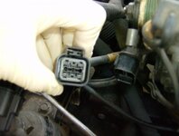
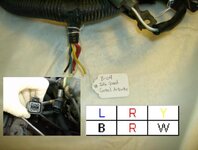
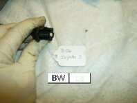
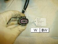
*****IMPORTANT*****
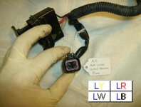
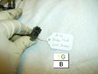
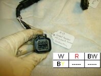
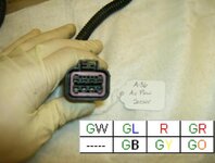
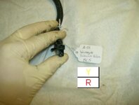
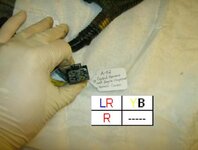
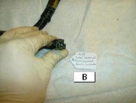
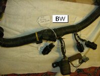
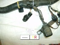
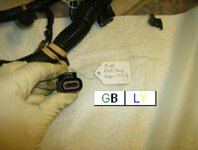
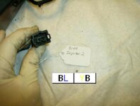
Note that the wire color layout diagrams accompanying each picture are as seen FROM the CONTROL HARNESS SIDE of the connector with the release tab (for a male side connector) or locking notch (for a female side connector) on top. That is, you are looking at the wires going into the connector, OPPOSITE the side that is pictured. Like this: How to identify ECU pin numbers.*******************
This is the ENGINE CONTROL harness. If you want information on the ENGINE COMPARTMENT harness, see: The 1990 Engine COMPARTMENT Wiring Harness.
As we all know, the 1990 model year had many quirks to it when compared to the later model 1Gs. Because this was a single (and the first) year of the Eclipse/Talon/Laser trio, information on these cars isn't nearly as abundant as 1991-1994 models.
I don't plan to dive into and explain the differences between these models as there are plenty of threads around naming the differences. In short, this article is a configuration diagram. It aims to familiarize members with the 1990 4G63 turbo engine control harness electrical connections, similar to what snowborder714 did in his 2g Engine Bay Electrical Connections article, but not nearly as thorough. To be clear, this article does not cover every electrical connection in the 1990 engine bay, only those on the engine control harness, including the handful of interior connections. For your convenience, the 1991 configuration diagrams are provided.
You must be logged in to view this image or video.
You must be logged in to view this image or video.
You must be logged in to view this image or video.
You must be logged in to view this image or video.
As a couple extras, it will touch on some connector differences that must be attended to when swapping a 1990 turbo engine control harness into a later model 1G or vice versa (these are denoted by **). It lists original wire colors and original individual wire locations as viewed from the wire side of the connector as well as a visual of each connector on the harness.
Also, for comparison, here is a similar page for the later model 1Gs (those connectors labeled with * are either completely different, in a different location, or non-existent on the later model 1Gs): 1Gb DSM 4G63 Turbo Wiring Harness Diagram
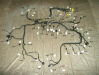
First and foremost, the main harness itself. The alphanumeric identifiers relate to those in the 1991 configuration diagram found in the electronic copy of the factory service manual: Download the 1G Service Manuals. The harness displayed here is a 1990 turbo engine harness which, by consequence, means it is from a vehicle with a manual transmission.
Click to enlarge slightly or zoom by pressing Control and + (the plus sign):
You must be logged in to view this image or video.
To shrink, press Control and - (the minus or negative sign).
A-08: Dual Pressure Switch (black connector, 2-pin)
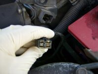
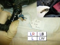
A-09: Wiper Motor (black connector, wide rectangular 4-pin)
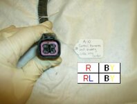
A-10: Control Wiring Harness and Battery Cable Assembly Combination / Starter Wiring Harness and Reverse Light Switch (black connector, square 4-pin)
*A-11: Auto-Cruise Control Actuator (black connector, square 4-pin)
A-12: Brake Fluid Level Sensor (black connector, stacked 2-pin)
A-13: Control Wiring Harness and Solenoid Valve Harness Assembly Combination (black connector, rectangular 6-pin)
A-36: Air Flow Sensor (black connector, NT 6-pin, Turbo 8-pin)
A-51: Waste Gate Solenoid (black connector, stacked 2-pin)
A-52: Control Wiring Harness and Engine Compartment Wiring Harness Combination (black connector, wide rectangular 4-pin)
A-53: Control Wiring Harness and Engine Compartment Wiring harness Combination (black connector, large 1-pin)
A-55: Fuel Pump Check Connector (black connector, small 1-pin)
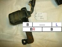
A-56: Noise Condenser (black connector, very small 1-pin)
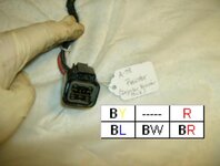
A-57: Defogger Relay (black connector, 5-pin)
A-58: Injector Resistor Pack (black connector, rectangular 6-pin)
A-59: Engine Speed Adjustment Connector (black connector, small 1-pin)
A-60: Ignition Timing Adjustment Connector (black connector, 2-pin)
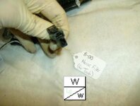
*B-00: Noise Filter (for Tachometer) (black connector, stacked 2-pin)
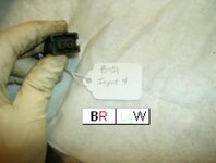
B-01: Injector No. 4 (black connector, 2-pin)
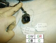
*B-02 & B-05: Throttle Position Sensor and Idle Switch (black connector, square 4-pin)
**B-04: Idle Speed Control Actuator (black connector, rectangular 6-pin)
B-06: Injector No. 3 (black connector, 2-pin)
B-07: Detonation (Knock) Sensor (grey / gray connector, 2-pin)
B-08: EGR Temperature Sensor (black connector, 2-pin)
B-09: Injector No. 2 (black connector, 2-pin)
B-10: Injector No. 1 (black connector, 2-pin)
*B-14: Ignition Coil (Coil Pack) (black connector, square 4-pin)
*B-15: Power Transistor Unit (black connector, straight 6-pin)
B-16: A/C Magnetic Clutch (black connector, round 1-pin)
B-26: Oxygen (O2, 02) Sensor (black connector, round 4-pin)
B-29: Engine Coolant Temperature Gauge Unit (black connector, small 1-pin)
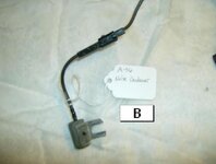
B-30: Engine Coolant Temperature Sensor (for ECU) (black connector, stacked 2-pin)
B-31: Engine Coolant Temperature Switch (for A/C) (black connector, 2-pin)
*B-32: Crank Angle and Top Dead Center Sensor (Cam Angle Sensor, CAS) (black connector, square 4-pin)
C-56: Oxygen (O2, 02) Sensor Check Connector (milk white connector, small 1-pin)
C-57: Control Wiring Harness and Body Wiring Harness Combination (milk white connector, 1-pin, passenger side kick panel)
**C-58: Control Wiring Harness and Body Wiring Harness Combination (white connector, 16-pin, passenger side kick panel)
C-59: Control Wiring Harness and Body Wiring Harness Combination (milk white connector, 6-pin, passenger side kick panel)
C-63: MPI Control Relay (milk white connector, 10-pin)
C-64: MPI Control Unit (ECU, small connector) (yellow connector, 10-pin)
C-65: MPI Control Unit (ECU, medium connector) (yellow connector, 18-pin)
**C-66: MPI Control Unit (ECU, large connector) (yellow connector, 24-pin)
**C-67: Control Wiring Harness and Body Wiring Harness Combination (under center console) (white connector, 8-pin)
The wire color layout diagrams accompanying each picture are as seen FROM the HARNESS SIDE of the connector with the release tab (for a male side connector) or locking notch (for a female side connector) on top. They should be color coded correctly, but if there is a disagreement with the letters and the color of the letters, go by the letters. When two colors are listed together, the first is the main color and the second is the color of the stripe or tracer. The letters represent the following colors:
B - Black
W - White
R - Red
G - Green
L - Blue
Y - Yellow
O - Orange
Lg – Light Green
PM me if you find any errors and I will make corrections as necessary.
Finally, the following supporting vendors supply the individual connectors linked or partial kits for different model year DSMs:
JNZ Tuning
Extreme PSI
Magnus Motorsports
At the end of the day, they are all coming from Sheridan Engineering.
You must be logged in to view this image or video.
Attachments
Last edited:


