The Top DSM Community on the Web

For 1990-1999 Mitsubishi Eclipse, Eagle Talon, Plymouth Laser, and Galant VR-4 Owners. Log in to remove most ads.

Please Support STM Tuned
Please Support Morrison Fabrication

This site may earn a commission from merchant
affiliate links, including eBay, Amazon, and others.

This site may earn a commission from merchant affiliate links, including eBay, Amazon, and others.

sacrileger

Proven Member
288
43
Jun 26, 2016
Orillia, ON_Canada
I am refurbishing my old alternator which most likely failed due to worn out brushes; however, just to make sure, i am testing all the inner components: the rotor, stator and rectifier. Testing the stator and rotor was pretty straight forward but i found testing the md133171 rectifier challenging.

I watched a bunch of vids on how to test alternator components and i found the vid below to be the most comprehensive and concise:
You must be logged in to view this image or video.

as can be seen in the vid above, the rectifier which the dude is testing is not constructed in the same way as the md133171 rectifier:
You must be logged in to view this image or video.


while i eventually did get all the correct values i was supposed to after a few trials and errors, i'd like to be certain that i tested this rectifier correctly and wanted to ask if anybody here would have a link to resources, such as vids or step-by-step procedure, showing how to test this particular (md133171) rectifier... as well as the ones which are coded as follows:
MD133171
MD136839
MD136838
MD133513
MD169683
MD169683D
MD158495
 
I wonder if this is a difference between the anemic 65A or barely useful 75A from the US cars and the 90A alternators the Canadian Turbo cars received.

Perhaps the 90A has an extra phase to increase the current?
i was thinking the same thing once i noticed vendors were selling alternators which looked physically the same but were marketed with different ratings (see my reply to @We're on Boost above). i'll have to figure out how to bench test this theory.
 
I see the 4 wires in your picture that look like they are coming from the stator. They look funny though. Each one looks like a twisted pair. What's with that?
good catch with the "twisted pair" wires!!
check out the unit below... single wire, three phase stator and rectifier with 4 terminals.... it definitely has to do something with the amp output. i vaguely remember that voltage/ampere output had to do something with how much copper is on each coil so i was not clear what 4 phases are to do with it but now i am thinking it has something to do with both
You must be logged in to view this image or video.
 
The alternators used for the 90A and those 110A version used in the 3S cars have the 4 wires. What I discovered is that it's not really a fourth phase but what's referred to as "Alternator with Neutral sampling". The common point of the Wye windings is brought out and rectified. I don't claim to understand ATM but here one description I found at https://youronlinemechanic.com/alternator-with-neutral-point-voltage/

Neutral-point voltage

(1) A conventional alternator uses six diodes to rectify three-phase AC (Alternating Current) into DC (Direct Current). The output voltages generated at the neutral point is utilized as a power source for the charge warning light relay. It is known that the average voltage of the neutral point is 1/2 of the output DC voltage. While the output current is flowing through the alternator, the voltage at the neutral point is mostly DC, but it also includes an AC portion.

The AC portion is induced in each phase by the flow of output current. When the alternator speed exceeds 2,000 to 3,000 rpm, the peak value of this AC portion exceeds the DC output voltage.

(2) This means that, compared with the output characteristics of the alternator without neutral-point diodes, the output gradually increases from midway by 10 to 15% at a normal rated alternator speed of approx. 5,000 rpm.

Alternator with Neutral-Point Diodes

Circuitry and construction

In order to add the potential variation at this neutral point to the DC voltage output by the alternator with neutral-point diodes, two rectification diodes are provided between output terminal (B) and ground (E) and connected to the neutral point. These diodes are installed in the rectifier holder.
 
The alternators used for the 90A and those 110A version used in the 3S cars have the 4 wires. What I discovered is that it's not really a fourth phase but what's referred to as "Alternator with Neutral sampling". The common point of the Wye windings is brought out and rectified. I don't claim to understand ATM but here one description I found at https://youronlinemechanic.com/alternator-with-neutral-point-voltage/

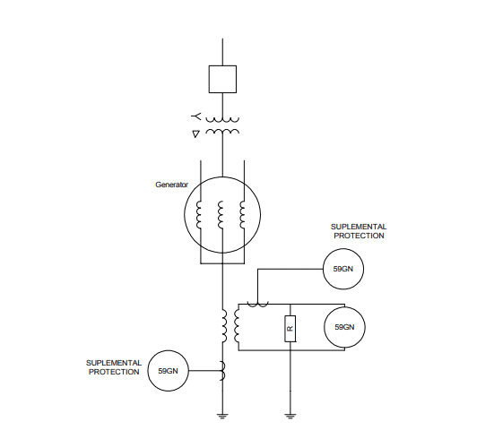
great find! it would appear that the neutral voltage is used to protect the alternator/generator stator winding from stator earth fault, according to this link:


needless to say, i am not clear why not all alternator with the 4th wire and terminal on the rectifier are not wired up to protect the winding from the stator earth fault.

i guess the theory that the forth wire is there to boost amp output is out the window...
 
Holy cow you guys I was just about to give up on the whole thing because it's getting too complicated and then what happens - I run into this video of a girl rebuilding a large generator, 3 phases plus neutral labeled U V W and N right on the name plate.

When she is winding the new coils you can kind of see that each coil is 2 wires in parallel I think. So that would probably be just to get the gauge, 2 smaller gauges in parallel instead of one huge thick gauge that would not wind as easily. You can start to see this at 4:53. Then again at 5:04. Then at 6:23 she is slipping paper tubes over the pairs, then scrapes the varnish off the ends and solders them together, and I get a little lost there with what is connecting to what.

What a bunch of stuff, I wish I had energy like this. If you've ever heard of building a bonfire inside the stator to get it apart, that is in here. Her micrometer, OMG.

You must be logged in to view this image or video.
 
I think you might be looking at something else.

Read section 2.1 of https://www.intechopen.com/chapters/38166 which describes this additional connection for increasing the output current.
i'll have to read more and figure out how exactly the neutral point increases output rather than protect the stator from grounding. the section 2.1 talks about "other auxiliary diodes connected BETWEEN the neutral point and the main rectifier":

In the alternators with wye connected windings, two or more other auxiliary diodes are connected between the neutral point and the main rectifier output terminals. In this way it is possible to rectify the induced third harmonic voltage and increase the output current at high speeds.

however, section 4.2.1 talks about winding reconfiguration which improves output power and efficiency:

One solution is to divide each phase winding in several coil groups and to modify the winding configuration by using several switches. It is then possible to obtain different connections of the coil groups (parallel, series, delta, wye) as a function of the speed.

the vid below (2nd part of 3) actually show how to rewire automotive alternator for higher output:

You must be logged in to view this image or video.

which leads me to believe the 4th wire is more for protection than increasing output; however, i am still not clear why my alternators are not hooked up that way even though the stators have 4th wire (neutral point) and the rectifier has the terminal for it.

furthermore, as i am noticing, when the neutral point wire is connected to the rectifier, the configuration is different so it's not like all it takes is to hook up the 4th wire to the 3rd terminal counting from the capacitor. there appears to be more to it...

If you've ever heard of building a bonfire inside the stator to get it apart, that is in here.
removing wires by building a bonfire inside the stator appears to be a standard practice. i had seen a similar vid with a barefoot pakistani dude burning off the insulation in automotive alternator in what looked like bbq and then installing new wiring by wrapping it around a wooden block... i just cant find the vid now.

i wish i had that girl's high powered soldering iron... my 25W soldering iron used for fixing circuit boards is not ideal for melting old soldered joints, i.e. disconnecting the rectifier from the stator
 
i'll have to read more and figure out how exactly the neutral point increases output rather than protect the stator from grounding. the section 2.1 talks about "other auxiliary diodes connected BETWEEN the neutral point and the main rectifier":

however, section 4.2.1 talks about winding reconfiguration which improves output power and efficiency:

If you look at the diagram you see that it's adding a set of diodes to from the center of the Wye configuration to the same places as the diodes from the other end of the coils.

In 4.2.1 it talks about completely different wiring configurations possible with the addition of switches to change the configuration as a function of speed. Completely different situation than the typical auto alternator.

the vid below (2nd part of 3) actually show how to rewire automotive alternator for higher output:

You must be logged in to view this image or video.

which leads me to believe the 4th wire is more for protection than increasing output; however, i am still not clear why my alternators are not hooked up that way even though the stators have 4th wire (neutral point) and the rectifier has the terminal for it.

furthermore, as i am noticing, when the neutral point wire is connected to the rectifier, the configuration is different so it's not like all it takes is to hook up the 4th wire to the 3rd terminal counting from the capacitor. there appears to be more to it...

If you watch the first video in that series he's taking a high amp alternator that originally was build as a Wye configuration and splitting the coils to configure it as a Delta configuration to increase the amps while reducing the voltage. Again a different process with it's own Pros and Cons.

i wish i had that girl's high powered soldering iron... my 25W soldering iron used for fixing circuit boards is not ideal for melting old soldered joints, i.e. disconnecting the rectifier from the stator

I had to buy a 100W Iron to solder the connections. I used to have a nice Ungar 100W tip that I used to build slot cars back in grade school but it didn't make in into the 21 century.

I've expended my time allocation for Alternators and learned more than I wanted to know. I hope you get to the bottom of the differences and fill us all in.
 
I'm getting a little interested in the idea of building an external regulator from scratch using diodes that have 2 or 3 times the current rating of the ones in the alternator. Can you think of any reason why it would be hard to build and use an external regulator?
in case you were still thinking about building your own external regulator, here's a vid how to do it including links and brief description:

You must be logged in to view this image or video.

Output voltage depends on which zener diode you use. Use a 12 or 13 V zener for charging (1) 12v lead acid battery, and use a 25-27V zener for charging (2) 12V lead acid batteries in series, OR use a 6V -6.2V zener to charge a 6v lead acid battery. You may have to adjust the value of the 1.5K resistor in the schematic to get the 2n3904 to work properly.

Schematic from: http://chemelec.com/Projects/Alternator/Alternator-Reg.htm

You must be logged in to view this image or video.


For the schematic shown in this video he used a 3.7K in place of the 1.5K, 900 ohms instead of the 1K, (2) 250V - 2.2uF electrolytic caps instead, and (2) zeners in series to get a total of 12.7V which gives the output of 14.7V.
 
Yeah that video and the description field has a lot of good info. I would have no idea how to make this kind of regulator without something like that. I mean, building something to manage the output of the stator by modulating the small current that goes through the rotor, I'd have no idea. Or maybe I'd buy one of the regulators we looked at earlier, which are pretty compact. But then I wouldn't know how to fix it if it bonked out.
 
I would agree that the main cause for failure is heat and/or fluids in the body of the alternator.

speaking of alternators failing due to fluids getting into alternators. i was changing a timing belt recently, power steering fluid found its way to slip rings, created conducting surface and shorted the brushes which caught on fire. here's what it looks like:

You must be logged in to view this image or video.
 
Step one, disconnect battery.ROFL
 
Support Vendors who Support the DSM Community
Boosted Fabrication ECM Tuning ExtremePSI Fuel Injector Clinic Innovation Products Jacks Transmissions JNZ Tuning Kiggly Racing Morrison Fabrications MyMitsubishiStore.com RixRacing RockAuto RTM Racing STM Tuned

Latest posts

Build Thread Updates

Vendor Updates

Latest Classifieds

Back
Top