The Top DSM Community on the Web

For 1990-1999 Mitsubishi Eclipse, Eagle Talon, Plymouth Laser, and Galant VR-4 Owners. Log in to remove most ads.

Please Support STM Tuned
Please Support Rix Racing

Rate my Porting

This site may earn a commission from merchant
affiliate links, including eBay, Amazon, and others.

This site may earn a commission from merchant affiliate links, including eBay, Amazon, and others.

Fox1486

15+ Year Contributor
131
4
Jul 10, 2004
Rochester, New_York
I picked up a EvoIII 16g and am going to run the stock boost for now. Hence I found it needs to be ported out. I've been reading Chadillac2000's writeup on "How to solve boost creep by porting" and the entire discussion with him and Oldman on another thread. Anyways I went out and bought a carbide burr, and have been porting for about 4 hours or so. I just finished, so I think, and started to smooth some stuff out with a stone bit.

Now it's time for everyone's favorite game........RATE MY PORTING!


Before porting:
You must be logged in to view this image or video.

You must be logged in to view this image or video.


After porting:
You must be logged in to view this image or video.

You must be logged in to view this image or video.

You must be logged in to view this image or video.


Now I still have to port out the area above the flapper arm to achieve the 90 degree opening, but I'm not as worried about that. I'm more concerned about porting TOO MUCH on the inlet and wastegate inlet and making the housing too thin. Anyone grade this for me/tips? Thanks

-Fox:dsm:
 
i would port the turbine inlet a little more, you can still see the step. Then get something to smooth it out nice. What does the flapper hole look like?
 
Thanks!

Honestly with the bit I have it is sooooo difficult to take that lip off any further. I don't really want to hit the outside which is 7cm.

Hows the top of the wastegate inlet??? That's my biggest concern.

What does the flapper hole look like?

I didn't port that out.......didn't read that I had to. Plus I didn't want to nick the flapper or where the flapper sits on the opening.
 
Go to home depot and get some 'cross buff's' :thumb: Pictures always make the surface look rough, but in reality it's not. Just try to get the scoring smooth so that you can't catch it with your finger nail. A 'liquid metal' port job is not required, ya know?
 
with all the well documented problems people have with 16G:talon:s creepin. How large is your turbo to exhaust manifold outlet? How large is your turbo to exhaust manifold gasket? Making everything the same size would be ideal. Maybe just a bit smoother with the anding crosses.
 
How large is your turbo to exhaust manifold outlet? How large is your turbo to exhaust manifold gasket? Making everything the same size would be ideal.

7cm. 7cm. I have an EvoIII manifold which is 7cm stock so I'm not going to port it any further. The outer rim of the turbo stock is 7cm. The O2 housing is the only thing that is not "EvoIII", so I need to port that out somewhat.
 
IMO it looks pretty good. What type of carbide bur are you using? The "flame" or "tree" shape seems to be good for all around use. With a cylinder style you can't really remove the whole step without grinding into the top of the flange.

The wastegate entrance looks good so far, you removed a good amount of material above it so the bottom lip can "catch" the exhaust flow. I can't tell if you did from the pictures, but you will want to radius the top of the wastegate passage as well. Be careful if you go much farther, the evo3 "lightweight" style casting doesn't have as much extra material as normal 7cm^2 housings. Check often so it doesn't get too thin or even grind through.

I wouldn't "gasket match," but rather make the smaller opening the same size as the larger opening. The gasket is often larger than the port itself, and hogging it out to match the gasket only to neck back down again is pointless. You want smooth bends that maintain a consistent diameter-always remember this while porting. It's also a good practice to make the entrance of each piece *slightly* larger than the exit of the one before it. This is because they don't always align perfectly, and it's easier for air to be dumped into a slightly larger area than forced into a smaller one with ledges sticking up around the edges. For example the manifold collector to the turbine inlet, the turbine inlet would be slightly larger than the manifold exit, say 1mm. This way there will be no corners sticking into the flow even if when you bolt it up they aren't aligned perfectly.

EDIT: Also, the flapper doesn't open 90*. The wastegate actuator is what holds it back, and ends up opening it to ~30*.

Getting the flapper to open 90* does however make it easier to port the wastegate passage to better match the flapper. Don't go too far though, leave some overlap so the flapper will still seal when it's closed; otherwise you'll hurt your spool time.
 
These are great points

What type of carbide bur are you using? The "flame" or "tree" shape seems to be good for all around use. With a cylinder style you can't really remove the whole step without grinding into the top of the flange.

Yep......its the cylinder style :toobad: That's why it's very difficult to get that step out

The wastegate entrance looks good so far, you removed a good amount of material above it so the bottom lip can "catch" the exhaust flow. I can't tell if you did from the pictures, but you will want to radius the top of the wastegate passage as well. Be careful if you go much farther, the evo3 "lightweight" style casting doesn't have as much extra material as normal 7cm^2 housings. Check often so it doesn't get too thin or even grind through.

I like how you described it, "Catch" the exhuast flow. That's exactly what I was going for. Noone had actually described it as such in the write-ups, but I gathered this is what the ultimate goal was.

As far as adding a "radius" to the top of the passage, I'm not quite sure what you mean. Do you mean the underneath part which you cannot see by looking straight down the turbine inlet? Or do you mean the side of the inlet itself where I ported out the material? I don't feel that comfortable porting more away. My biggest fear is that the material will be too thin and crack due to heat/pressure.

It's also a good practice to make the entrance of each piece *slightly* larger than the exit of the one before it.

I've tried to keep to this while porting.

Getting the flapper to open 90* does however make it easier to port the wastegate passage to better match the flapper. Don't go too far though, leave some overlap so the flapper will still seal when it's closed; otherwise you'll hurt your spool time.

I think if I was going to port the actual passage through the flapper side of the turbine housing, I may just use a stone bit instead of carbide. It seems to be important to keep this pretty symmetric in order to keep the flapper closed. I may just smooth this out rather than taking away more material.

Thanks a bunch for that :thumb:
 
As far as adding a "radius" to the top of the passage, I'm not quite sure what you mean. Do you mean the underneath part which you cannot see by looking straight down the turbine inlet? Or do you mean the side of the inlet itself where I ported out the material? I don't feel that comfortable porting more away. My biggest fear is that the material will be too thin and crack due to heat/pressure.

Glad to help!

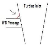
Here's a picture. Not to scale, not pretty, but hopefully gets the point across a little better.

The radius part is in red, although hard to tell...

You only want to do this at the top, and be sure you don't go too far and hit the seat of the flapper.

By the way, for just using a cylinder style, very nice job :thumb: Not that it didn't look great to begin with, you can't really ask for anything more.
Once in a while you'll dig the edge in and make a knick in the metal, especially when it's not a convex surface. You probably know what I'm talking about :p
 

Attachments

  • radius.JPG
    radius.JPG
    4.3 KB · Views: 579
thanks.

I was just out there smoothing some stuff out. Cut a slot into the end of a short rod that I fit into the air grinder. Then I cut a strip of sandpaper, feed one end in the slot, and wrapped the rest down the rod. Then I took some duct tape and taped it on securely. Sprayed some WD-40 on both the sandpaper and on the inlet. Within about 5 minutes the inlet was so smooth and shiny!!! Works wonders. Beats sanding by hand.

Glad to help!

Here's a picture. Not to scale, not pretty, but hopefully gets the point across a little better.

YES!!!! Awesome, I did do this. I thought since we were getting rid of the "90*" turn into the passage, it should be a smooth transition. Thanks for the diagram.

Here's some pics of the turbine inlet after smoothing it out with the sandpaper last night:

You must be logged in to view this image or video.

You must be logged in to view this image or video.

You must be logged in to view this image or video.


I took off some material above the flapper arm in order to increase the angle in which the flapper opens:


Before:
You must be logged in to view this image or video.

You must be logged in to view this image or video.


After:
You must be logged in to view this image or video.

You must be logged in to view this image or video.

You must be logged in to view this image or video.


It may not look like much, but when you look at the flapper straight on you can see the difference.

Almost done with the O2 housing......
 
fyi, at full boost, the wastegate door only opens up to about a 45* angle AT MAX. Porting the arm for a 90* opening is pretty moot. I would leave the wastegate hole alone. It's pretty tempting to open up the wastegate hole more, but in my experience it's not worth the risk of creating cracks in the housing. Work on that lip more, though.
 
Yeah I'm done with the wastegate hole. I'm not gonna remove anymore of the lilp. I know it looks noticeable in the pictures, but honestly it seems not even measurable in person. Just with the bit I have it's pretty impossible to get it without grinding away at the top of the flange.
 
I'm not sure if Tom was talking about the lip at the inlet or by the wastegate flapper, but you want to hit that as well.

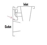
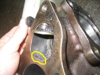
You don't want to change the flange at all, just take that corner out of the housing(only the lightweight castings have it). You want to blend it in so the gases won't get hung up on that ledge. When the flapper is fully open(~30*) most of the flow is directed right at that point and I feel it's important not to have the lip there. Even if it only helps a tiny bit, it's easy to shave down.

The line is red is what you want it to look like when finished.
 

Attachments

  • portinglip.JPG
    portinglip.JPG
    7.9 KB · Views: 520
  • 16glip.jpg
    16glip.jpg
    49 KB · Views: 522
You have a nice steady hand and it shows. If you can't get rid of that lip with the head you're using switch to something different. And since it's a 16g take out that corner in the wastegate area. Better flow-->more flow--> uninterrupted flow=no or little boost creep.:talon:
 
Looks pretty damn good, man. That's exactly what I was talking about with the WG exit.

Is the o2 housing outlet matched to your donwpipe? That's a 1g o2 housing isn't it? Do you have any shots of where the WG passage goes back into the exhaust flow from the outlet side of the o2 housing?
 
It is not matched to the downpipe as that is still on the car. Didn't know if there was a difference between the 1g and 2g O2 housing, but that makes sense since the guy who I bought my 14b from gave it to me. I didn't really "port" this as much as I did trying to clean up all the uneven portions. Obviously material was taken off, but as far as the outlet of the O2 housing, I don't think there was much difference that it won't match up.

Here is a pic of the wastegate gas mating back with the rest. One of my air grinders died in the process of porting this portion out (figures), so I have to use a 90* tool that had even more limit on the reach inside. Again I tried my best to file it down, but I wasn't sure how prone these were to cracking:
You must be logged in to view this image or video.
 
Most people get rid of the lip at the outlet, but they often match it to their 2.5" downpipe as well. I'm not sure if you have the stock one or not, if so I don't think it's too big of a deal.

1g and 2g o2 housings look nearly identical to me(on the inside) besides the placement of the o2 sensor, the 2g has it at the base and the 1g has it near the top. You should be fine as far as porting goes for that.
 
Support Vendors who Support the DSM Community
Boosted Fabrication ECM Tuning ExtremePSI Fuel Injector Clinic Innovation Products Jacks Transmissions JNZ Tuning Kiggly Racing Morrison Fabrications MyMitsubishiStore.com RixRacing RockAuto RTM Racing STM Tuned

Latest posts

Build Thread Updates

Vendor Updates

Latest Classifieds

Back
Top