The Top DSM Community on the Web

For 1990-1999 Mitsubishi Eclipse, Eagle Talon, Plymouth Laser, and Galant VR-4 Owners. Log in to remove most ads.

Please Support Morrison Fabrications
Please Support ExtremePSI

1G Dynatec arc 2 install no spark HELP!!

This site may earn a commission from merchant
affiliate links, including eBay, Amazon, and others.

This site may earn a commission from merchant affiliate links, including eBay, Amazon, and others.

Right now I would recommend that you put it back to stock and try to get spark on both coils and troubleshoot from there. In your first picture, the bottom bolts both left and right need to see +12v to them with the key on and engine off, we might be looking in the wrong area, for that matter I assumed that this car was running prior to you installing the Arc2, if it wasn't you could have a bad cas or something like that.
 
Right now I would recommend that you put it back to stock and try to get spark on both coils and troubleshoot from there. In your first picture, the bottom bolts both left and right need to see +12v to them with the key on and engine off, we might be looking in the wrong area, for that matter I assumed that this car was running prior to you installing the Arc2, if it wasn't you could have a bad cas or something like that.
Neither of the bottom bolts have 12 v of that was the case i wouldnt have spark on either coil. Yes that where i am at is converting back to no dynatek and see where im at. Also if i dont re attatch the tacho interface wires when switching back to stock will it cause any issues as far as spark? Or am i understanding this correctly. The tacho interface white red and yellow are soley for rpm signal to cluster.
 
I would hook the tach interface back up, I don't have a 90' coil here handy to look at and I really can't see all of the wires on your coils so I am kind of guessing where all of the wires go to on your coils, in any case you will have a jumper wire somewhere on each coil that connects 12v from one coil to the other, it looks to me like that is the wire on the bottom bolts from here, if it is then there needs to be 12v on that wire, if I'm not seeing it right then its one of the other wires but in any case one of the carries 12v to one bolt on each coil, the ignition transistor fires the coil by grounding the other side of the coils.
 
Last edited:
I would hook the tach interface back up, I don't have a 90' coil here handy to look at and I really can't see all of the wires on your coils so I am kind of guessing where all of the wires go to on your coils, in any case you will have a jumper wire somewhere on each coil that connects 12v from one coil to the other, it looks to me like that is the wire on the bottom bolts from here, if it is then there needs to be 12v on that wire, if I'm not seeing it right then its one of the other wires but in any case one of the carries 12v to one bolt on each coil, the ignition transistor fires the coil by grounding the other side of the coils.
There is NOT a wire on my coils that has 12v! Not even coming out of the arc2 box. So im assuming it cannot be detected via a meter
 
That yellow wire wont matter Manny. If it is built to plug and play just unplug the Arc box and plug it back in stock. The ONLY thing that won't work is the tach, the rest of the system is meant to do just what you are doing. If my Arc box went out, I can just unplug it and plug the coils back in and it runs fine, just no tach.
 
That yellow wire wont matter Manny. If it is built to plug and play just unplug the Arc box and plug it back in stock. The ONLY thing that won't work is the tach, the rest of the system is meant to do just what you are doing. If my Arc box went out, I can just unplug it and plug the coils back in and it runs fine, ok i will give that a shot. If i still dont have spark on 1&4 what would be the first culprit? Cas or coil?
 
I would hook the tach interface back up, I don't have a 90' coil here handy to look at and I really can't see all of the wires on your coils so I am kind of guessing where all of the wires go to on your coils, in any case you will have a jumper wire somewhere on each coil that connects 12v from one coil to the other, it looks to me like that is the wire on the bottom bolts from here, if it is then there needs to be 12v on that wire, if I'm not seeing it right then its one of the other wires but in any case one of the carries 12v to one bolt on each coil, the ignition transistor fires the coil by grounding the other side of the coils.

Sitting here thinking. The original tacho interface does tie the 2 coils together. But according to everyone its just for rpm signal to tacho. Should i just install a set of coils out of a 91+
 
Deleted the arc box out of picture and re installed the tacho interface. Same coil 1-4 is dead. Also tested the Power transister unit and its good.

Finally i swapped the coil triggers red and white wires and now the coil 1-4 has spark and 2-3 is dead. Im lost here.

Also ensured good pin tension and continuity in CAS and COIL connectors.
 
How have you checked the power transistor? have you checked your ecu? how about swapping in a known good cas?
 
How have you checked the power transistor? have you checked your ecu? how about swapping in a known good cas?
I followed a post on here. I actually put lightbulb and loaded the circuit. According to the instructions it checks good. No i have not swapped the CAS. Is there a way to test that with a dvom?
 
You would need an oscilloscope to actually test the cas in any meaningful way, tell me do you have fuel injector pulse on all four injectors?
 
You would need an oscilloscope to actually test the cas in any meaningful way, tell me do you have fuel injector pulse on all four injectors?
Thats what i figured i dont have access to a o scope. As for the injector pulse i have not checked yet. How would i go about testing that? Noid light or can a meter be used.
 
Noid light or a 12v test light, you check each one while cranking, this should eliminate the cas as a problem if it checks out.
 
What I would do is use a couple of hat pins or small needles to insert into the injector connectors so that you can then easily touch them with your test light, they just need unplugged from the injectors to do the test at the connector, just be very sure not to allow the hat pins or needles if you use them to touch each other or ground out on anything, it can ruin your ecu instantly!!! I would lay an old towel down so that nothing can ground out for that matter.
 
What I would do is use a couple of hat pins or small needles to insert into the injector connectors so that you can then easily touch them with your test light, they just need unplugged from the injectors to do the test at the connector, just be very sure not to allow the hat pins or needles if you use them to touch each other or ground out on anything, it can ruin your ecu instantly!!! I would lay an old towel down so that nothing can ground out for that matter.

So let me get this right. Only 1 of the pins will pulse right? Or do i need to attatch 1 side of test light to 1 pin and the other to 2nd pin?
 
Update: i have injector pulse on all 4 cylinders. Verified by installing a old injector i had from my evo 8. They fire 2 times per 1 turn of CAS.

Also tested CAS 4 pulses on cam wire and 2 pulses on tdc. All at 5.0 volts
 
BINGO!!!!

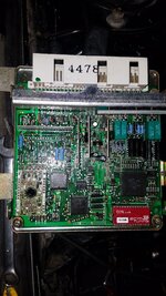
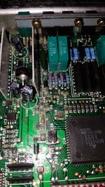
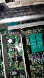
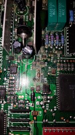
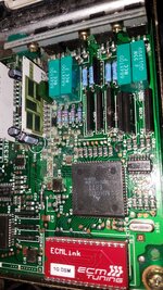
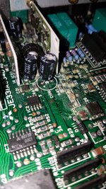
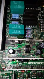
Pulled put ecm have lots of capacitor leakage all over circuit board!! Pictures attatched


Who can fix this? Or do i need a new ecu?
Thanks for all the input MARTY and Matt
 

Attachments

  • 15784454393397846827154834945121.jpg
    15784454393397846827154834945121.jpg
    1.7 MB · Views: 43
  • 15784454596751896217644785051980.jpg
    15784454596751896217644785051980.jpg
    1.6 MB · Views: 33
  • 15784454752892765551115453251888.jpg
    15784454752892765551115453251888.jpg
    1.3 MB · Views: 40
  • 1578445489284395761317991896711.jpg
    1578445489284395761317991896711.jpg
    1.6 MB · Views: 39
  • 15784455056591833187234864080818.jpg
    15784455056591833187234864080818.jpg
    1.8 MB · Views: 38
  • 15784455305346622562850250725470.jpg
    15784455305346622562850250725470.jpg
    1.4 MB · Views: 36
  • 15784455523865863533289729472609.jpg
    15784455523865863533289729472609.jpg
    1.3 MB · Views: 40
There looks like enough component damage on that board to justify finding a replacement, the guys at Dsmlink used to do repairs, you might try them for repair or replacement.
 
UPDATE: Dave Mertz over at ecmlink fixed the leaky capacitors. He bench tested the ecu and could not verify my concern. So went back to the drawing board. Performed continuity and resistance tests from ECU &PTU. All wires good under 0.5 ohms of resistance. No open wires or high resistance. So also tested wires from CAS to ECU all wires tested GOOD under 0.6 ohms EXCEPT the white wire reads 3.0 ohms from CAS to ECU.

Then i moved back to PTU and found the pins in the actual PTU to be White seems to be Oxidation. So i added lime juice to the pins and cleaned them with a connector cleaner file. Now the pins are copper colored again.

I will be receiving the ecu from ecmlink tomorrow so i am unsure if this fixed the issue.

I will keep this updated in case other users come across this in the future.
 
Support Vendors who Support the DSM Community
Boosted Fabrication ECM Tuning ExtremePSI Fuel Injector Clinic Innovation Products Jacks Transmissions JNZ Tuning Kiggly Racing Morrison Fabrications MyMitsubishiStore.com RixRacing RockAuto RTM Racing STM Tuned

Latest posts

Build Thread Updates

Vendor Updates

Latest Classifieds

Back
Top