

JFZERO ECLIPSE
15+ Year Contributor
- 749
- 11
- Jul 20, 2004
-
Altoona,
Pennsylvania
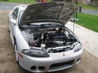
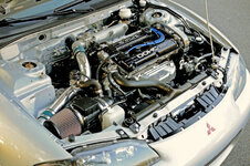
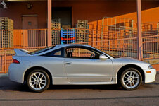
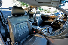
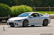
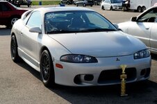
Beautiful looking car, and It's amazing how much stuff can be removed....If I were you I would opt for a complete ss clutch line from master to slave...Iw would get rid of 1 bracket and a bunch of hard line
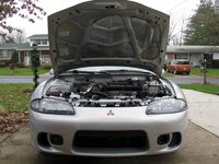
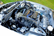
 If I did eliminate abs the lines would be ran low on the firewall and would probably be stainless steel tubing.


")
 . Also at random times the front brakes feel like they go out and the break pedal goes to the floor and you almost rear end people.