The Top DSM Community on the Web

For 1990-1999 Mitsubishi Eclipse, Eagle Talon, Plymouth Laser, and Galant VR-4 Owners. Log in to remove most ads.

Please Support Fuel Injector Clinic
Please Support STM Tuned

ISC - where to buy, how to check wiring harness.

This site may earn a commission from merchant
affiliate links, including eBay, Amazon, and others.

This site may earn a commission from merchant affiliate links, including eBay, Amazon, and others.

alIan

20+ Year Contributor
164
0
Oct 17, 2002
Thousand_Oaks_CA_(near_LA)
I narrowed down my idle surge to my ISC , for sure (put in an old non-functional ISC at fully closed step, and surge went away completely). I have two questions:

1) How can i check the wiring harness to the ISC to make sure it is fully functional? The coils seem to all check out just fine in the ISC motor... I am sure the wiring harness is at least PARTIALLY functional, since i can hear vibration and see movement in the ISC when the key is turned from off to on (as the vfaq says).

2) where can i buy a functional ISC for a decent price (i hate satan) if it turns out that is not the harness? I'm sure some of you have found better deals than the dealer... ($349 here in thousand oaks, CA).

Thanks

Ian
 
Get an ohm meter and check the wiring with the battery disconnected. Check out the classifieds or your local salvage yard. The 1g N/t isc motors work as well
 
I got mine from NAPA. It definitely wasn't $350.
 
iscs from mid 90s mirage/galants also work, i forgot which car and year specifically, but I know because thats what I replaced mine with from what I found in the junk yard. Just bring yours so you can compare the size.
 
There is a guy on Ebay who does ISC rebuilds for like $80 + core. He did mine 2 years ago and it has not given me a problem at all.

/edit found info

The guys ebay name is vince1887, it looks like he upped his price to $139 for the rebuilt ISC but hes got one on auction right now.
 
If the coil windings check out the ISC usually works in a system that's working.
I replace one or more ISC drivers in about 25% of ECUs that show up here. Most of the time the owners didn't know they were bad because they weren't seriously burnt up,

There are various ways to test the wiring harness but you do need a multimeter. You can either disconnect everything and measure the end to end resistance of each wire or check to see that voltage is present on each of the 4 wires at the ECU end when the MPI circuit is active.

When I get some time I want to make a video showing the difference between a good ISC stepping and a bad one. A good ISC desn't really vibrate much as it's rehomed by the ECU on powerup.

Steve
 
steve said:
If the coil windings check out the ISC usually works in a system that's working.
I replace one or more ISC drivers in about 25% of ECUs that show up here. Most of the time the owners didn't know they were bad because they weren't seriously burnt up,

There are various ways to test the wiring harness but you do need a multimeter. You can either disconnect everything and measure the end to end resistance of each wire or check to see that voltage is present on each of the 4 wires at the ECU end when the MPI circuit is active.

When I get some time I want to make a video showing the difference between a good ISC stepping and a bad one. A good ISC desn't really vibrate much as it's rehomed by the ECU on powerup.

Steve
That's coming from the best dsm electronics expert I know. Listen when he talks:thumb:
 
Steve do you think you could give me more detailed instructions on how to do the tests you named for the wiring? I have access to a multimeter and know a lil bit about electronics. I just need it spelled out as far as which wires to test for the car specifically :).

Also, a video of the good/bad ISC step would help a lot..

Thanks!

-I

P.S. the "new" ISC i have IS one that was rebuilt by the guy from ebay...
 
steve said:
I replace one or more ISC drivers in about 25% of ECUs that show up here. Most of the time the owners didn't know they were bad because they weren't seriously burnt up,
Steve
Steve what does a failing ISC driver act like when running in a car? I have replaced my isc with a good one, fixed all my leaks, adjusted everything till I turn crazy, and my car will still dip a little up and down from 500-1000 rpms when my car is all warmed up. I've been battling this the whole time I have had the car. I have almost given up on having a good idling car. Could my MAS be causing something? Just before it idles funny my stock boost gauge will go from the bottom -14 to -7 and move up and down, then it idles funny. Any thoughts? Thanks.
 
talontsi18 said:
Steve what does a failing ISC driver act like when running in a car? I have replaced my isc with a good one, fixed all my leaks, adjusted everything till I turn crazy, and my car will still dip a little up and down from 500-1000 rpms when my car is all warmed up. I've been battling this the whole time I have had the car. I have almost given up on having a good idling car. Could my MAS be causing something? Just before it idles funny my stock boost gauge will go from the bottom -14 to -7 and move up and down, then it idles funny. Any thoughts? Thanks.
make sure the ground that goes from your firewall to your intake manifold is connected good. Also you might try blocking your fiav.
 
I would also like to know how to quickly and easily (if possible) check the ECU for a bad ISC directing component... and i would love to know which wires to test for the harness (i.e. where to test them exactly with the multimeter).
 
If the coil windings check out the ISC usually works in a system that's working.
I replace one or more ISC drivers in about 25% of ECUs that show up here. Most of the time the owners didn't know they were bad because they weren't seriously burnt up,

There are various ways to test the wiring harness but you do need a multimeter. You can either disconnect everything and measure the end to end resistance of each wire or check to see that voltage is present on each of the 4 wires at the ECU end when the MPI circuit is active.

When I get some time I want to make a video showing the difference between a good ISC stepping and a bad one. A good ISC desn't really vibrate much as it's rehomed by the ECU on powerup.

Steve
Hey Steve, just found this thread. Where can I find more information about how to test the resistance from end to end, and the voltage at the ECU? I think I have a wiring issue. Thanks
 
To test the cars wiring with a multimeter you first need to make up some extension clips so your meter's probes can reach both ends of the wire. Since one end is at the middle of the dash and the other end is in the engine bay it will need to be at least 6-10ft long and unless you have a helper it should have alligator clips on the ends so you don't have to grow longs extra arms.

Next is to understand how your multimeter works. How do you select resistance measurements? What does it display for shorted probes and open ones. How do you select voltage measurements? Does the meter have ranges for it's measurements or is it autoranging?

Third is make sure you have the wiring diagrams that apply. If you have a bastard car with mixed years make sure you have all the diagrams and note which applies to what. I print out pages for the garage to write on and expect them to get dirty not my manuals.

For voltage measurements in the car one probe is likely grounded (usually the black) and the other is connected to the place you want to measure the voltage of relative to ground. Check for voltages first before making any resistance measurements so you don't damage the meter.

For resistance measurements both probes are connected one at each end and your usually looking for shorts (zero of close to zero ohms) and opens (infinite ohms or very high ohms in the mega range).

In the ECU/ISC case, disconnect both the ECU and ISC from their harnesses. Measure each of the 6 ISC pins on the wiring harness. The two middle ones (91+ connector) get battery voltage when the MPI circuit is active and act as the power source for the ISC coils while the ECU grounds the other side via the remaining 4 pins in order, but for this test everything should be off and there shouldn't be any voltage to speak of on any of the pins. Then set up to measure resistance. Again one pin at a time measure the resistance of each pin/wire from the harness side of ECU connector to the matching harness side of the ISC connector, also measure to make sure the wire isn't shorted to one of the other pins or to ground. IIRC, the 90 swaps the order of the which ISC coil on one half is connected to which ECU driver pin. If you have a 90 ECU with a 91+ ISC you need to account for that.

Keep in mind that when you flip over a connector the right and left sides swap. The wiring diagrams show locations based on looking at the back of the connector where the wires enter or looking into a socket where the pins are facing you.
Understood thanks man! Just ordered an auto range multimeter. Amazon prime baby. I found a thread concerning the switches polarity in the 90s-91s ISC wiring. Going to give that a look over tomorrow and see if I can’t figure this out.
 
You'll need to swap the black and white isc wires when extending the harness as well as oblong the holes a bit and flip the isc 180 degrees. Just did it last season.
Here is the thread I’m following basically telling me everything you are saying: http://www.dsmtuners.com/threads/1990-isc-motor-–-reverse-polarity-for-new-part.514056/

However, I’ve found an issue when testing the ISC with ignition on, it only vibrated. It does not go in nor out. Also I don’t have to extend the harness. It easily reaches. I’ll have to check to make sure the wires are in the correct position. If not, then I’ll check continuity and that I’m getting correct voltage from the MPI relay when I get my multimeter.
 
Mine did that exact thing when it was bad. Is this a new isc? If not test the coils when your meter is in if it's bad and your in a pinch I got mine at autozone they had it in stock it was like 80$. I can try and get some pictures off my ISC with what I did if you need.
 
Mine did that exact thing when it was bad. Is this a new isc? If not test the coils when your meter is in if it's bad and your in a pinch I got mine at autozone they had it in stock it was like 80$. I can try and get some pictures off my ISC with what I did if you need.
It’s not a new ISC, but I’ve tested the coils on all three of mine and they tested good. They are the new black top motors, that have a resistance near 40 ohms. I bought this one from someone who took a video of them testing it on their harness and ohm testing it before I purchased it. And that would be very helpful, thank you!
 
I'll look today after work I know it's a tight spot. I'm not saying yours is bad but mine tested within spec also but it wiped the caps because it was bad a new isc was my fix I'd be sure you check with the steps Steve posted he's way smarter than me it could be shotty wires.
 
I'll look today after work I know it's a tight spot. I'm not saying yours is bad but mine tested within spec also but it wiped the caps because it was bad a new isc was my fix I'd be sure you check with the steps Steve posted he's way smarter than me it could be shotty wires.
I think it may be wiring as well. I went ahead and swapped pins 67 and 68 at the ECU. Still doing the same thing.
 
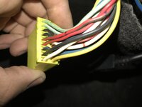
Here is a picture I took after swapping the pins at the ECU. I swapped the white(originally pin 67) with the black (originally pin 68).

Looking at a thread Steve was in a while back in 2013, he was saying to swap the wires at the ISC side (4 and 6). I swapped the ECU pins. Effectively, did I do the same thing? Or is there a reason to swap the pins at the ISC motor and not the ECU?
 

Attachments

  • 963E9416-7312-4D3E-AF11-1C99690F42CB.jpeg
    963E9416-7312-4D3E-AF11-1C99690F42CB.jpeg
    233 KB · Views: 127
Going through the service manual, I've found this. It says, "Check that when the ignition switch is placed in the ON position, the operating sound of the stepper motor can be heard over the idle speed control servo."

This is only telling me to ensure I can hear the motor, not telling me to verify the plunger going in or out for proper operation. However, from what I've been told, the plunger has to go in/out with ignition on/off. I also could be reading this wrong because it's saying I need to hear motor operation over the servo. I thought the servo was the motor:banghead:. Regardless, I get my multimeter tomorrow and I'll test the harness for continuity.
 

Attachments

  • ISC troubleshooting.PNG
    ISC troubleshooting.PNG
    26.2 KB · Views: 172
Support Vendors who Support the DSM Community
Boosted Fabrication ECM Tuning ExtremePSI Fuel Injector Clinic Innovation Products Jacks Transmissions JNZ Tuning Kiggly Racing Morrison Fabrications MyMitsubishiStore.com RixRacing RockAuto RTM Racing STM Tuned

Latest posts

Build Thread Updates

Vendor Updates

Latest Classifieds

Back
Top