This document is intended to be a step by step guide to configuring a Megasquirt board, creating a wiring harness for the car, and getting MS to run in a DSM. This document could not be possible without the help of Jerry at diyautotune and Scott (dieselgeek). Thanks a lot for your help.
Now you may be wondering what Megasquirt is and what can it do. It is basically a stand alone engine management system comparable to an AEM system. Megasquirt uses a MAP sensor and an intake air temperature sensor to calculate fuel needs based on displacement. This is referred to as a speed-density setup. That sounds like it should be expensive doesnt it? Well the programming is all freeware, so the only cost is the board and the components. You can get the entire kit for around 190 dollars. You can not really beat the options with MS without spending a good amount more. If you install spark and fuel, then you can remove the MAF, which has a few benefits.
Some of the features of Megasquirt Extra:
12x12 fuel tables
12x12 spark tables
Rev limiter
Overboost protection
Anti-rev / Traction Control feature
Knock sensor input
Launch Control/Flat shift
A complete list can be viewed at the Megasquirt and Spark Extra page. A few of these require additional circuits and hardware, but it is not hard to add them.
Required Reading before you decide if you want to tackle installing MS.
Diyautotunes site
http://www.diyautotune.com/tech_art...your_4g63_powered_dsm_eclipse_talon_laser.htm
Official Megasquirt home page.
http://www.megasquirt.info/
Megasquirt and Spark Extra
http://megasquirt.sourceforge.net/extra/
If you decide that you can handle installing MS, go ahead and order a prebuilt board or the kit.
Components you need not in the kit:
3 1k ohm ¼ Watt resistors
2 470 ohm ¼ Watt resistors
I recommend buying the kit and putting it together yourself. You will learn a great deal and will find it much easier to add in other components later on, such as boost control or water injection. The components come clearly labeled, and if you can follow simple instructions its fairly easy to build the basic board. The megastim is also recommended; since it will help you troubleshoot before you actually install MS into the car. It is a lot easier to troubleshoot the install if you know the MS is working in the first place. It is also a great starting point for a complete beginner at soldering.
Alright, so you ordered the kit and are ready to build the board. Go to this page http://www.megasquirt.info/ms2/V3assemble.htm and follow steps 1-49.
That was fun wasnt it? Step 50 requires you to configure the board to a DSM specific setup. The DSM uses an Opto setup and does not trigger off of the negative side, so you only need to do part A.
ONLY DO STEP 50A.
If you are feeling overly ambitious, you can continue with step 51 and install the VR circuit, but it is not required to run. I personally did not bother installing the additional circuitry because I never plan on using this MS in another car.
Now that the circuitry is there, you need to configure the jumpers. Do step 52 and only use the jumpers for the Hall sensor, optical sensor
1)Jumper XG1 to XG2 on the bottom side of the PCB, near the 40 pin socket,
2)Jumper OPTOIN to TACHSELECT on the bottom side of the PCB, near the DB37
3)connector, opposite the heat sink.
4)Jumper TSEL to OPTOOUT on the bottom side of the PCB, near the center.
Now continue on with step 53 until the end. There are no more jumpers to put into place in those instructions. Every jumper mentioned is for MSII and not needed for MSI.
Alright, you remember those extra resistors I told you to get in the beginning? You finally get to put those on.
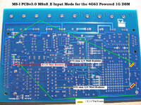
3 of them are required to condition the crank and cam signal so that MS can work with it.
A good diagram for showing just exactly how they are put on can be seen at the diyautotune site.
http://www.diyautotune.com/images/cartech_articles/4g63/ms1_v3_msns-e_4g63_input-mods.jpg
The next part is to use those extra 1k ohm resistors to condition the board to use the stock ignitor. Its really simple, take the resistor, leave about ¼ of an inch lead, hook both ends and loop them around the pins that were already soldered. The picture below shows where they go. The resistor goes from the 5v side of each resistor to the negative leg of the respective LED. This is then brought over to the db37 with a length of wire. The top resistor goes to IGN and the bottom resistor goes to IAC2B. Congratulations, your board is now complete and you can start on the wiring fun. The next part will be to construct a wiring harness.
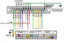
A pinout with the ecu and db37 harness will be posted later on.


