The Top DSM Community on the Web

For 1990-1999 Mitsubishi Eclipse, Eagle Talon, Plymouth Laser, and Galant VR-4 Owners. Log in to remove most ads.

Please Support STM Tuned
Please Support Fuel Injector Clinic

Head gasket/Timing belt/60k Maintenance... How does everything look?

This site may earn a commission from merchant
affiliate links, including eBay, Amazon, and others.

This site may earn a commission from merchant affiliate links, including eBay, Amazon, and others.

PFC_CiarlilloM

10+ Year Contributor
234
0
May 22, 2011
Euclid, Ohio
Alright so long story short, my head gasket went on me, and being unsure of the age of the timing belt I decided it was time for a timing belt/60k maintenance job as well for piece of mind.

Vehicle Info;
1996 Eclipse GSX
(7 Bolt motor)
140k w/ auto

*Supposed to be rebuilt by the previous owner of the guy I bought it off of, said to have around 40k on it, but no receipt = very skeptical*

So being my first tear down of a vehicle, I took my sweet old time tearing everything down, and labeling every bolt, connector, etc.

I put piston #1 to TDC according to the timing marks that were on the vehicle, saw the piston through the spark plug hole, verified by putting the oil dipstick down, and felt it. Removed both belts, finally removed the pulleys, and timing auto tensioner (replacing 60k/timing maintenance)

SIDE NOTE,
*Both (OEM) belts looked really good, the pulley's looked great too when wiped off, and comparing them to my OEM pulleys. So maybe the engine was really rebuilt, but timing belt components aren't good enough to make that assumption*

I kinda stumbled upon something that I thought was weird. The head bolts looked aftermarket, at first a 13mm 6pt fit just nice, and snug, but then in spun, so I went to get a 13mm 12pt (thinking they were ARP) but that was too big. A 12mm 12pt was what it ended up being. :hmm:

So I assumed that they were ARP's for a 6 bolt. (Went and rechecked my oil pan.. had the dent, so its a 7 bolt) Well when I finally removed them I put my 7 bolt ARPs in the thread and they fit nice and perfect, also the bolts that came out didnt have "ARP" stamped anywhere on it. So they weren't 6 bolt 12mm ARP's. WTF

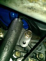
After what seemed like forever, I finally got everything removed, and prepped to pull the head... but it wouldn't pull up..... Damn intake manifold bracket, it will get you every time LOL. It was a PITA to remove and its definitely not going back in. (P.O said the owner before him rebuilt the motor *supposed to be around 40k on the rebuild*... was kinda hoping he removed it but I guess not)

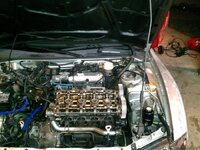
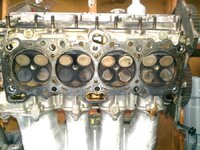
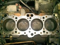
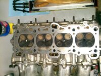
So I finally got the head off, I'm not sure how the head gasket would look being my first pull, and just started working on cars, but it didn't appear to look great in my eyes. The cylinder walls looked really good, no scoring, and it looked like I could see my reflection in them. The pistons just looked like they had some carbon build up, but somehow piston #1 isnt at TDC anymore. The all appear midstroke.

From here I am cleaning everything up to put on my Felpro composite (Part No. HS 9627 PT-3) head gasket, ARP headstuds, gates water pump, and OEM timing belt/components using @BogusSVO's method's (http://www.dsmtuners.com/forums/cylinder-head-short-block/413772-how-clean-head-gasket-surface.html)
(http://www.dsmtuners.com/forums/new...r-how-clean-block-deck-pistons-installed.html)

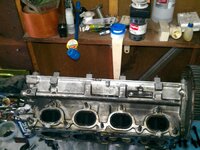
Just wanted to see what you guys think just going off the pictures I attached, as well as any helpful tips or advice.
 

Attachments

  • IMG_20120714_220700.jpg
    IMG_20120714_220700.jpg
    72.9 KB · Views: 82
  • IMG_20120716_163916.jpg
    IMG_20120716_163916.jpg
    64.1 KB · Views: 82
  • IMG_20120716_164140.jpg
    IMG_20120716_164140.jpg
    75.5 KB · Views: 83
  • IMG_20120716_172450.jpg
    IMG_20120716_172450.jpg
    62.6 KB · Views: 87
  • IMG_20120716_174539.jpg
    IMG_20120716_174539.jpg
    56.2 KB · Views: 81
  • IMG_20120716_224949.jpg
    IMG_20120716_224949.jpg
    66.9 KB · Views: 79
Last edited:
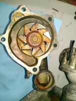
I would flush the coolant system and replace water pump. Looks like it ran tap water. Should use distilled water or a 50/50 mix.
 
Were the old head bolts you pulled studs or actual bolts? Did you move the car at all once the timing components were off, that could cause the crank to turn. You might also be able to tell if he rebuilt it if the balance shafts are gone, not saying if they are there he didn't, but if they are not then he probably had the engine out.
 
@TSITurbo95 I was thinking tap water was used by the previous owners going off what the water pump looked like. Rest assured, I've only used distilled water since I had it, and will only use distilled water even if I'm just flushing it. I bought a new gates OEM water pump, and will continue to use distilled. I also flushed it prior to the tear down to determine if it was a head gasket because I was getting a milky color. I was just hoping the milky color would have gone away after but it returned. The water pipe has a lot of that red paste that was found in the water pump inside it as well.

@jls_frog They were actual bolts. Those are aftermarket right? I believe I read that OEM for both 6/7 bolt motors had a 10mm bolt head. Anyways, I havent actually moved the car yet. I left the timing components where they were, and haven't rotated the crank. I havent checked the balance shafts yet, but the balance shaft belt is still installed, so I am assuming that the shafts are still in place.

Why/how would piston #1 go from TDC to midstroke after removing the head. Is it my error, or is this normal?
 
Last edited:
The bolts still could be aftermarket just not arp, for instance rock auto sales fel-pro head bolts for the 4g63. if the balance shaft belt is still there then yes the balance shafts are still there. The pistons could have possibly moved due to gravity, but i have never seen it personally on an engine that has been running. My Honda engine when i was rebuilding it would end up like that if i left it sitting on the engine stand before i put the head on it.
 
nope. the OEM head bolts are 12mm 12pt.
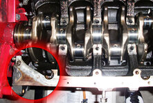
you can also read the code on the block surface. if its there chances are it hasn't been resurfaced. the code represents what bearings/tolerances where used during assembly.
 
@jls_frog That's what I was assuming, but wanted to confirm. They do look really similar to the ARPs I bought, but since I didn't install the ones I pulled, I'll just use the ARP's I bought. I actually bought the gates water pump, and felpro head gasket set/kit from rock auto. I should have bought the BSE kit but for now I'll just replace the belt and pulley.

@born2tune Thanks for clearing up the confusion regarding the head bolts. I havent found any code stamped on the block surface yet.
 
Last edited:
That's what I was assuming but wanted to confirm. They do look really similar to the ARPs I bought, but since I didn't install the ones I pulled, I'll just use the ARP's I bought. I actually bought the gates water pump and felpro head gasket set/kit from rock auto. I should have bought the BSE kit but for now I'll just replace the belt and pulley.

@born2tune thanks for clearing up the confusion regarding the head bolts. I havent found any code stamped on the block surface yet.

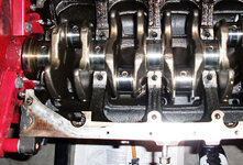
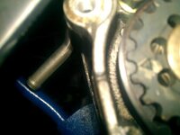
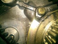
sorry I had a retard moment, I was trying to find exactly where I found the code to show you, and its NOT on the top surface on the block, its where the oil pan meets the block surface. pic posted. Sorry for the confusion, its been a minute since I got deep into the engine stuff...
That's what I was assuming but wanted to confirm. They do look really similar to the ARPs I bought, but since I didn't install the ones I pulled, I'll just use the ARP's I bought. I actually bought the gates water pump and felpro head gasket set/kit from rock auto. I should have bought the BSE kit but for now I'll just replace the belt and pulley.

@born2tune thanks for clearing up the confusion regarding the head bolts. I havent found any code stamped on the block surface yet.

sorry I had a retard moment, I was trying to find exactly where I found the code to show you, and its NOT on the top surface on the block:banghead:, its where the oil pan meets the block surface. pic posted. Sorry for the confusion, its been a minute since I got deep into the engine stuff...
 

Attachments

  • CIMG1952.jpg
    CIMG1952.jpg
    84.5 KB · Views: 72
  • CIMG1952a.jpg
    CIMG1952a.jpg
    85.2 KB · Views: 67
@born2tune Don't worry, it's all good. I was just re-reading everything, and realized I had so many grammatical errors.... screw being a grammar Nazi when I type LOL. Anyways, I didn't actually think it was stamped on the deck, but thanks for posting up that pic. So in order to see if that "code" is still there, I have to pull the oil pan?

Also I am having a hell of a time getting the block/head aligning dowel pins off!!! I read BogusSVO's method, but I cant find a 1/4 drive socket that fits. I tried a 9mm, and its just a tad big. I'm afraid that if I tap it with a hammer, it'll either get stuck in or I'll damage the dowel pin itself. Any tips?

Quick question; When the camshaft sprockets are in correct time, should all the valves be closed?
The reason I am asking is when I pulled the head, after putting piston #1 to TDC, I noticed that a couple of valves weren't fully closed. Ill post up a pic to show what I mean.
 
few things to point out:

- the dowels pins should be replaced if you have a hard time pulling them out. they are cheap so just make sure you dont damage the block in the process.

-You dont have to pull the oil pan off to read the code. but that code is for the bearings used on the crank. so my question is if you are not pulling the pan out then why worry about the code if you are not messing with the crank assembly?

- about the head- its a tricky answer, because once the timing belt is off they wont be naturally aligned, unless you turn it with a wrench by force because of the springs and the cam lobes, secondly the valves will not be all closed if you move the cam"in time" with the other one. although they will look like they are almost all closed,
remember, by looking at the cam shaft, all lobes are setup at different angles therefore there is no way all the valves will all close at the same time on that row(intake or exhaust).
 
@born2tune First off, thanks for all the advice. I guess I am just really paranoid, and don't want anything going wrong. I'd hate to do all this work, and find out that the new gasket still leaks, or something along those lines.

- I was actually going to call up the dealership tomorrow to see if they have them or can get them because the vice grips scored up one of them pretty good. I am sure I could work it out but like you said they are cheap. I found them online for $3, but don't want to wait for them to be shipped.

- I am planning on pulling the oil pan to redo the gasket while I take care of the transfer case/rear diff fluids. I guess I was just curious as to if it was still there or not.

- Thanks for the heads up about the head. Again I am just really paranoid among other things.
 
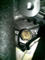
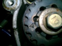
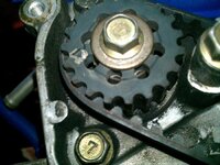
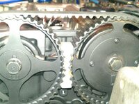
So, I finally got the balance shaft belt on, and just wanted to get your guys opinions on the timing marks. I tried my best to get a head on picture.

Also can someone elaborate a little bit more on step 34-36 on the VFAQ?
I am confused as to why I would torque the tensioner pulley bolt in step 32 only to loosen it in step 34.

I will post up pics of the all timing marks after I correctly install the timing belt.
 

Attachments

  • IMG_20120806_000403.jpg
    IMG_20120806_000403.jpg
    32.4 KB · Views: 72
  • dsm.jpg
    dsm.jpg
    79.4 KB · Views: 82
@born2tune/Albrecht09 - Thanks for the confirmation. I thought it looked good, but I wasn't sure, and I am not taking a chance of it "looking good" on something like the timing belt.

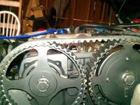
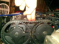
Okay so I attempted to install the timing belt and I am having issues with the tensioner pulley/auto tensioner/tensioner arm.

I am confused on steps 32-36 in the VFAQ. Step 32 has me torque down the pulley tensioner bolt down to 35 FT/LBS and then step 34 has me loosen the bolt. I am completely lost.

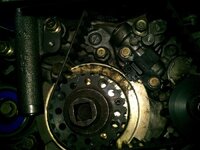
Here is how the belt looks right now, but I know its not right.
 

Attachments

  • IMG_20120806_210229.jpg
    IMG_20120806_210229.jpg
    53.7 KB · Views: 72
  • IMG_20120806_210148.jpg
    IMG_20120806_210148.jpg
    22.2 KB · Views: 73
  • IMG_20120806_210115.jpg
    IMG_20120806_210115.jpg
    35.5 KB · Views: 69
  • IMG_20120806_210048.jpg
    IMG_20120806_210048.jpg
    29.4 KB · Views: 66
  • IMG_20120806_205955.jpg
    IMG_20120806_205955.jpg
    55.3 KB · Views: 60
  • IMG_20120806_205759.jpg
    IMG_20120806_205759.jpg
    54.1 KB · Views: 62
  • IMG_20120806_205616.jpg
    IMG_20120806_205616.jpg
    59.6 KB · Views: 58
  • IMG_20120806_205451.jpg
    IMG_20120806_205451.jpg
    62.6 KB · Views: 76
  • IMG_20120806_205439.jpg
    IMG_20120806_205439.jpg
    54.6 KB · Views: 70
I didnt follow the Vfaq. I just follow the manufacturers shop manual.
and from what I remember what you do to it is keep the tensioner pulley bolt "loose" meaning not torqued to allow movement/pivoting.
then you torque the pivot bearing (2.6ftlbs if I recall correctly) then hold its position/tension in place, THEN torque the actual bolt while keeping the positive pressure applied to the pivot bearing nipples. after torquing the pivot into position and simultaneously torquing the pulley bolt afterwards, remove the hydraulic tensioning special tool/long ass bolt.
then you fully rotate the crank about 2-6 times and allow the hydraulic tensioner to stabilize, then it should protrude about 4.5mm, this would indicate a proper torque on the tensioner pulley. if its sticking out too much it means the pulley has been torqued at an angle way too tight. and if it sits below 43.8mm then its too loose.

-please look up the millimeter measurements and torque's as I don't remember exactly.

BTW horrible job on rattle canning the cam gears and valve cover and everything around it. If the engine is out you should address such discrepancies.
 
Just read through the whole thread and it looks like your doing a awesome job getting everything back together. I just wanted to ask if you put a machinists straight edge on the deck and head to make sure no machining was needed? It would be a hell of.a heart break to get it running just to.find out the headgasket blew again.
And thats ALOT of slack between the cam gears. If you start the belt at the intake cam and keep tension all they way around untill u get to the tensioner pulley you can get rid of that slack. Take hippies or plastic clamps and hold the belt in place on the cams. And i Dont see any timing marks on that belt.....no no LOL. Even if you make your own its a hell of a lot easier and gives You a little piece of mind.
 
PFC,

You have to set the tension with the tensioner pulley first, then pull the pin out of the auto/hydraulic tensioner. The tensioner pulley is the one on the left with the two "eye" holes.

When you set the tension on the timing belt correctly, you can pull the pin out of the auto/hydraulic tensioner and then put it right back in.

When setting the tension on the belt, via the tensioner pulley, I use a long, flat head, screwdriver and moderately pry against the pulley using the water pump as a pivot point. While holding some moderate tension there, tighten the 14mm bolt for the tensioner. The "eyes" on the pulley should be around 11 o'clock and 2 o'clock. Then pull the pin out of the auto tensioner...the piston will not protrude out of the top.


Try it and report back. GL!
 
Thanks everyone for the replies. I'll get back to everyone individually. My method is as follows;

Method;
*Used the following websites as a guide*
How to: Put Your 4g63 In Time - Team-2G Mitsubishi Forum
Timing Belt VFAQ

First I started with timing the Camshaft's and locked the sprocket holder in place. I wrapped the timing belt around the Intake Cam first, then I had to give a pretty good pull to get it seated in the Exhaust Cam properly. Then I followed by wrapping behind the Idler Pulley, the Oil Sprocket, the Crank Sprocket, and finally around the Tensioner Pulley. I had the two circles on the Tenioner Pulley to the left side, and then put tension on it until the were parrallel to ground.

Then I did steps 29-33 in the VFAQ. I put the Tensioner Tool in, and made contact with the Tensioner Arm. I turned a little past that as it stated, and pulled the grenade pin.(The pin was able to slide in and out w/out any effort) After that I rotated the Crank Sprocket about 1/4 counter-clockwise, then clockwise, and the timing marks still lined up correctly.

I made two revolutions, and everything was still in time besides the Oil Sprocket. At that point I loosened the Tensioner Pulley bolt, threaded the tensioner tool in the arm, and tried torquing it as close to 2.6 FT/LBS, and finally re-torqued the Tensioner Pulley bolt back to 35 FT/LBS (Step 34 VFAQ)

I let it sit for about 30 minutes, removed the threaded tensioner tool, cam sprocket holder, zip ties, and rotated the crank about 4-6 times. Everything was in "time" except the Oil Sprocket. The auto tensioner had the gap in the picture at that time.

For the Oil Sprocket, I rotated it until the arrow was facing up and rotated counter-clockwise towards the timing mark. I thought that was full proof method of ensuring it was in time.

Lastly, I was pushing down fairly hard on the top between the Cam Sprockets.

Anyways, I have to drive to work. Ill finish this when I get there (roughly about 10 minutes)

@born2tune - I initially had the tensioner bolt only hand tight to allow it to move easier. By pivot bolt are you talking about the bolt w/ the big washer that's connected on the tensioner arm? but I think I know my mistake now. Thanks for the advice! Ill try your method when I get off in the A.M. (Wish I could do it now LOL) Btw regarding the paint, the valve cover isn't finished and I noticed the paint coming off the sprockets when I checked the timing the last time. Its going to be covered anyways, but thanks for pointing that out.

@lou98gsx - I rotated the oil sprocket until it was at the 12 o'clock position, and fell counter-clockwise towards the timing mark. Isn't this full proof?

@onequicktsi - See above. I can't seem to find the plug hole. It seems easy on the diagram. Maybe I am just looking too hard for it.

@herms99gst - Thanks, I'm just trying to take care of everything the right way and not neglect anything. Plus since this is my first somewhat major tear down so I'm not trying to pick up any bad habits. I seriously have about 6000 plastic bags labeled specifically LOL. I couldn't get my hands on a machinist straight edge unfortunately. I should have waited but I took the closest/best straight edge I had and stuck a .006 feeler gauge under and it didn't pass in any spots. I really hope nothing major goes wrong when I start it (knock on wood) I was pushing down really hard to get that much deflection on top of the cam sprockets/gears. I had to give it a little bit of a stretch to get the belt to initially sit over the exhaust cam sprocket in the beginning. I didn't forget about the marks but thanks for catching that. I am waiting until its perfectly time and then ill mark the belt

@92Gsr- 4 - I originally set the tension on the pulley, then tightened the tensioned tool a little past when it made contact. When I did this I was able to pull the pin out and insert it w/ ease. I think my problem came after that as I pulled the pin (stated in VFAQ) then tried to torque the tension tool that was still in place 2.6 FT/LBS. Is this what I am supposed to torque? or do I torque the pivoting arm bolt ( one w/ huge washer) I have the tool with the two prongs to put tension on the pulley. 11 & 2? I thought it was 6 & 4 for 2g's?

@herm99gst - that's what I did!
 
Its at about 6-4 for 2gs. and no, not the pivot arm/the washer, thats a completely separate part.

if you torque the pulley and torque the pulley bolt correctly then the auto tensioner should read 3.8 to 4.5mm, otherwise it would read too much or too little indicating an improper torque. theres no other way to explain this.
 
@born2tune thanks for the advice. It finally hit me now atleast I'm pretty sure. I think I'm over-thinking everything.

From here, all I would do is compress the auto tensioner slowly using the special tensioning tool then just adjust the tensioner pulley accordingly right?
 
Support Vendors who Support the DSM Community
Boosted Fabrication ECM Tuning ExtremePSI Fuel Injector Clinic Innovation Products Jacks Transmissions JNZ Tuning Kiggly Racing Morrison Fabrications MyMitsubishiStore.com RixRacing RockAuto RTM Racing STM Tuned

Latest posts

Build Thread Updates

Vendor Updates

Latest Classifieds

Back
Top