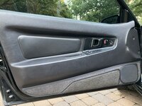
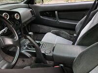
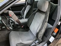
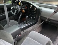
The Central Hub for DSM Community and Information

For 1990-1999 Mitsubishi Eclipse, Eagle Talon, Plymouth Laser, and Galant VR-4 Owners. This is where the DSM platform history is documented and archived. Log in to help us in our mission, and to remove most ads from the browsing experience.

IMG_4563.jpeg

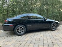
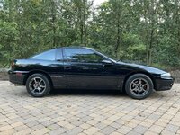
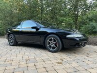
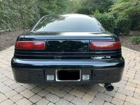
93 Laser

This site may earn a commission from merchant affiliate links, including eBay, Amazon, and others.

I didn't buy it from Florida.

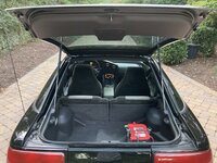
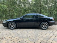
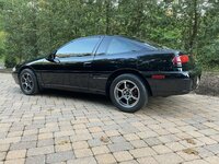
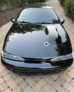
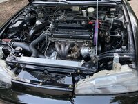
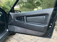
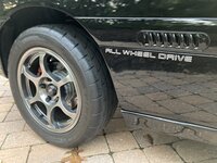
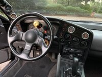
Here it is the day it arrived. Very clean car.

3.jpg


2.jpg


1.jpg


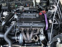
But right away I could tell this car needed some help. The throttle body had the ISC and FIAV deleted, so I had to sit in the car for over 5 minutes holding the throttle open so it would eventually, hopefully, catch idle. The CAS was clocked all the way clockwise, the throttle stop was set wrong, the tune was weird, and the alternator was basically dead. The twin disc clutch was QUITE the learning curve. Just getting it into the driveway I stalled it no joke 20 times. I can't imagine what the guy that delivered the car was thinking watching me fumble with it so bad. My buddy came over and he couldn't get a handle on it either, between the two of us was 40+ years driving a stick and we were hilariously bad at it. Some buyers remorse was kicking in.

After adjusting all the stuff I could and redoing the tune, the car became much more functional. I did manage to take it out for a few pulls and the car hauled ass despite an awful tune and whatever was going on with the base ign timing. An issue quickly popped up, it was eating through the 1"x1" relay block for the fuel pumps, they just kept burning up on every pull so that was the end of me driving it around.

I put it in storage for winter and decided to tackle the alternator that was giving me 11.3v. I did the Saturn alternator mod and rewired it entirely, along with using huge 0/1 gauge wire to and from the battery. This gave me the ~14v I was seeking. Nice! But, immediately this exposed the problem of the relay block for the fuel pumps. After only a minute of idle with proper voltage, the car smelled of fire and the relay block was literally melting.

9.jpg
 
Last edited:
Definitely not kchaaz’s Laser, but as I look at his car I love the way he did the sound system in the trunk. I've wanted bumps for 25 years so I may go for it and mimic his design there.

-

So the next battle is going about the fuel pump relay. I guess the easy way out is to put in a bigger relay, but that just doesn't sit right with me. The wires are the size of spaghetti and I was curious what was going on in there so I ended up pulling the entire assembly - which sucked. First of all, the -10 feed and -8 return lines on this $FullBlown$ hanger are too close together. 1mm would have made a giant difference. It was a game of turning one line a hair so the part of the fitting where the wrench goes was flat in correlation with the other one so I could get a fraction of a turn there, and back and forth. It felt like I was doing one of those simple brain challenge puzzles and it took me 30 min to work through. Not a good start.

image000000 (2).jpg


Once the lines were off, the assembly wouldn't come out as two 450's next to each other are about 1/8" too wide to slide through the circle opening in the tank. I noticed that whoever was in here before kinda ovaled the opening, so I worked off that and after much frustration it did come out.

Here's the Walbro wires. Weaksauce.

image000swf006.jpg


assembly pulled

image00sadf0005 (1).jpg


Time for some serious improvement.
 
Last edited:
First things first, get 2 proper bulkheads for the proper gauge wiring to pass through the assembly.

10.jpg


I bought a new gasket for between the tank and assembly as I simply needed one and I realized I'm down to the mm on making this stuff work so wanted the gasket to be true and round to dictate the modifications. Grinding on this hanger - and the float assembly - is not for the faint of heart as the hanger is over 400 bucks so now we're playing with it's value there, and the grinding on the float is within less than a millimeter from clearancing it too far and it being junk.

11.jpg

12.jpg


Ground side bulkhead. Stock, and even on this hanger, you can ground the pump internally on the assembly, but if you think about it, it is in the tank isolated from any ground by rubber gasket. I am going to ground the pumps directly to the battery terminal which is in the trunk (probably the only positive of putting the battery in the trunk). Anyways, here's that.

13.jpg

14.jpg

15.jpg


I now have the ability to run large gauge wire directly to the pump. And by directly, I mean directly. Above is the virgin 450, below is the wiring part of the modification to the pump itself.

16.jpg


Cleaned up, I have now eliminated the Walbro wires and exposed a big footprint to do my own thing.

17.jpg


Stock Walbro 450 wire VS my new wire. This is 8 gauge PTFE wire safe for E85. If I had to do this again I would use 6 gauge. But 8 is plenty and I see no issues.

Just look at that difference.

18.jpg
 
Last edited:
Repurposed my Walbro connector; one wire for the float and the other for the low fuel sensor. Previously the low fuel sensor was -- grounded?. Not a big deal I guess, but that needed to be corrected.

19.jpg


Punched in the relief valves with stainless hardware. This is a must if you want to run high base fuel pressure and/or high boost. I've had these pop open on me in the mid to upper 70psi range which is bad news running "stock" base fuel pressure and boost into the 30s. I plan to run both much higher so this mod is a requirement.

20.jpg


Soldered and sealed the wiring to the 450's. This is PTFE wiring rated for e85 and it is NICE to work with. I've never paid attention to the quality of wire before, just the gauge. There's no going back after using this stuff. Sealant is clear this time rated for e85 unlike our trusty JBWeld.

21.jpg


I forgot to take a picture of the pump itself completed, but here's a picture of the pump on my other car just for reference. This is the way it should have come from Walbro IMO.

24.jpg


And here's a little more on punching in the relief valve now that I've dug up the old pictures. Here's the location of the hole and the depth of the bolt (~18mm). If you use a slightly undersized drill bit in relation to your bolt, the threads will catch nicely. I use the nut there for some redundancy.

25.jpg

26.jpg
 
I encountered a lot more clearancing to do, had to file the barbs off the walbro pumps which I remember doing in the past. No idea how people slide on high pressure fuel hose over those barbs. The studs for the bulkheads were just too short for my liking so I made some new ones, put loctite on every screw, fill FuelTech's channel for wiring with epoxy. Misc stuff here and there.

The one pump fit as predicted and the wires were perfect bends/length which was very satisfying.

27.jpg


Second pump in, slight clearance for the float to have full motion, quadruple check everything, and send it. I pulled the zipties tight after getting them in the tank as the clearance is negative getting them in there. But there it is, the all end all of a dual in-tank fuel setup. 8 gauge wire direct on pump units with correct bulkheads through the assembly to have a true 8 gauge the entire way with no corners cut, and the relief valves punched in. I guess the only improvement here would be to use 525 pumps instead, but one of these 450s got me to horsepower in the 700s, so two will be plenty of fuel no matter what I do.

28.jpg

Thing looks like a WOMD LOL, shame it'll be unseen from here forward and hopefully never, ever, ever pulled out.
 
I ordered a boost-a-pump which would put 22v to these pumps, but it was delayed in shipping and I'm not even sure I needed it anyways, so I just finished it to move onto something else. I can add it later if needed. I always wanted to try a BAP to the coil packs, so maybe I'll do that instead.

29.jpg


The relay mounted directly to predrilled holes and fit in there like it belonged.

30.jpg


And aside of the battery back there, which I hate, it's like nothing happened.

31.jpg
 
For years I have wanted to run a Saturn alternator and really experiment with the S wire. People were running different lengths and different gauges to different locations trying to achieve the desired output. I saw this as a huge opportunity to use a potentiometer. Snag was, I knew zero about potentiometers. I searched and asked around explaining what I was trying to do and just couldn't get a confident answer. Then I came across a video on youtube by @familyMAN . Ayy, I know that dude, so I watched as he put one on his car and that validated the idea. It was literally spoon-feeding me exactly what I was after. So, shout out to familyMAN for telling me what OHM pot to use as that was the _exact_ info I was after.

image000000 (2).jpg


image000000 (3).jpg
 
Last edited:
I encountered a lot more clearancing to do, had to file the barbs off the walbro pumps which I remember doing in the past. No idea how people slide on high pressure fuel hose over those barbs. The studs for the bulkheads were just too short for my liking so I made some new ones, put loctite on every screw, fill FuelTech's channel for wiring with epoxy. Misc stuff here and there.

The one pump fit as predicted and the wires were perfect bends/length which was very satisfying.

View attachment 734115

Second pump in, slight clearance for the float to have full motion, quadruple check everything, and send it. I pulled the zipties tight after getting them in the tank as the clearance is negative getting them in there. But there it is, the all end all of a dual in-tank fuel setup. 8 gauge wire direct on pump units with correct bulkheads through the assembly to have a true 8 gauge the entire way with no corners cut, and the relief valves punched in. I guess the only improvement here would be to use 525 pumps instead, but one of these 450s got me to horsepower in the 700s, so two will be plenty of fuel no matter what I do.

View attachment 734116
Thing looks like a WOMD LOL, shame it'll be unseen from here forward and hopefully never, ever, ever pulled out.
What do the relief valves in the top do? How do they work?
 
Think of it like a wastegate for the fuel pump.
Hmm..🤔 Still don't understand. Maybe when I get hands on with this part I will. Is it not just a bolt screwed into the plastic with a nut locking it in place? Does adjusting the depth of the bolt do something?
 
Last edited:
Subscribing. Interested to see where this beast goes!
Off topic but is that an observatory I spy in post#5? In YOUR HOUSE? That's epic!:hellyeah:
I was going to ask the same thing but didn't want to go off topic. Glad I wasn't the only one who was like wait a minute... ha
 
Dude I’d say you’re GOLDEN on fuel LOL, I’m running a full blown hanger with dual dw340’s, highest duty cycle I’ve seen on a gen 2 6266/e85 is 66% at 37-38psi, you’ve got a BEAUTIFUL car there, I think I like black 1gb lasers more than black 1gb talons now LOL
 
Off topic but is that an observatory I spy in post#5? In YOUR HOUSE? That's epic!:hellyeah:
Yep! Coolest thing I own hands down.

Hmm..🤔 Still don't understand. Maybe when I get hands on with this part I will. Is it not just a bolt screwed into the plastic with a nut locking it in place? Does adjusting the depth of the bolt do something?

The tip of the bolt keeps the relief valve from popping open. It wants to, but cannot. I do not know the design of the valve but will cut up my dead 450 to see. The depth is 18mm as that's where the contact of the tip of the bolt meets the valve. I think I went to 19/20mm this time and it was rather obvious when you hit the point you want.
There's enough plastic for the bolt to bite into and self thread. As for why the relief exists, I guess it was a design to keep the pump from over working. Like a wastegate on a stock turbo, there is a reason it's regulated at 10ish psi boost. My hole and bolt is the equivalent of welding the WG flapper shut. For 99% of operation it would be unnoticed. Only at WOT you see the difference.

Rather quickly Walbro came out with the 450 high-pressure, which I guess has it popping open in the 90s instead of 70s. But I will mod them shut always. If I run 42psi base fuel pressure and 55psi boost, I need my fuel pump to put out 97psi. Not for long, but I need it. If the pump quits sending fuel at 78psi, it's trash to me. I can have 10 pumps in the tank but if they all stop at 78psi I am dead in the water. So, the mod. And I only exceed that threshold for a couple seconds at a time during a rare WOT pull while it's bathed in e85, It's not a giant deal. If I was circuit racing or doing a half mile pull, I'd probably do an entirely different setup as Walbro seems to think the pump shouldn't live in that environment and I won't contest that much beyond what I'm doing.
 
Today I swapped out the TB.

What a stupid mod deleting the ISC and FIAV is. Maybe if you lived in the desert using only gas, I guess, maybe. The rest of us, I do not understand this.

Here's hungover whatever welds paired with make the inside smooth. This pipe is temp anyways. But it works!

image000000 (3).jpg


5.jpg


Done.
6.jpg


Turning the key after this was like starting a new car.
 
Last edited:
I’ve gone 2 years now without an isc/fiav on my s90 but I think I’m ready to look for a 91-94 isc LOL, for me It’s not terrible because I would let the car run for 5-7 minutes anyways to warm up, but it would be nice not to have to baby the throttle everytime before it goes into closed loop :)
 
Yep! Coolest thing I own hands down.


The tip of the bolt keeps the relief valve from popping open. It wants to, but cannot. I do not know the design of the valve but will cut up my dead 450 to see. The depth is 18mm as that's where the contact of the tip of the bolt meets the valve. I think I went to 19/20mm this time and it was rather obvious when you hit the point you want.
There's enough plastic for the bolt to bite into and self thread. As for why the relief exists, I guess it was a design to keep the pump from over working. Like a wastegate on a stock turbo, there is a reason it's regulated at 10ish psi boost. My hole and bolt is the equivalent of welding the WG flapper shut. For 99% of operation it would be unnoticed. Only at WOT you see the difference.

Rather quickly Walbro came out with the 450 high-pressure, which I guess has it popping open in the 90s instead of 70s. But I will mod them shut always. If I run 42psi base fuel pressure and 55psi boost, I need my fuel pump to put out 97psi. Not for long, but I need it. If the pump quits sending fuel at 78psi, it's trash to me. I can have 10 pumps in the tank but if they all stop at 78psi I am dead in the water. So, the mod. And I only exceed that threshold for a couple seconds at a time during a rare WOT pull while it's bathed in e85, It's not a giant deal. If I was circuit racing or doing a half mile pull, I'd probably do an entirely different setup as Walbro seems to think the pump shouldn't live in that environment and I won't contest that much beyond what I'm doing.
Thank you very much for this explanation I get it now. I’ll be running two 350s just not sure if this would be a good mod for me or not. Any downsides to doing this? Plan on running an FP Zero Ball Bearing btw…

I’ve gone 2 years now without an isc/fiav on my s90 but I think I’m ready to look for a 91-94 isc LOL, for me It’s not terrible because I would let the car run for 5-7 minutes anyways to warm up, but it would be nice not to have to baby the throttle everytime before it goes into closed loop :)
I got the Magnus remote mount iac adapter but it says for 2g. Also bought a few different versions of the stepper motors as I wasn’t sure which would work properly. Hopefully I’ll manage to get something working with y’all’s help..LOL
 
Any downsides to doing this? Plan on running an FP Zero Ball Bearing btw…

Only what I said. I wouldn't use this for circuit racing, or for long pulls where you're asking max effort out of the pump for a long time. I use this mod for like a second or two at a time.
The turbo used means zero point zero. This could be NA.


-


No eye candy updates to share, but I have been plugging away on this thing. I've gone from it idle surging, to it barely idling, to it working way too well with settings way too wrong. It really is a balance act and there's many constants to abide to with the variables having to be within reason, and you're reluctant to alter stuff to get to those constants when it is seemingly working too good. Weird dynamic there. But today I finally got it all dialed in which is a bit a journey of chasing your tail, and the car fires up immediately holding idle at 1krpm to the point you think the cluster is broken because it's dead nuts stable. It revs freely with no hiccup. Base timing is set, which caused me to change the idle cells a lot on the table in DA, but all is good as I know when I ask for timing at WOT it will be accurate - which is incredibly important if you're uninterested in popping the engine. The throttle stop is set, although this TB is foreign to me so while it performs perfectly I am a bit skeptical on the throttle stop to BISS relationship. Maybe some room for work there, but again it works perfectly. I loaded in the DA deadtime values from Tom and Dave's injector testing and wowowowowow. What a gift of information there. I left those values in DA and will never change it as that's the shape I want, I'll only globally adjust from there. Lots of back and forth on getting the global fuel correct until it lines up at peak VE with much adjustment to global deadtime to counteract that, but that is normal procedure. The car locked in openloop has afratioest and wb matched beautifully and at peak VE they match. That is a calibrated fuel system.
I am now to the point of having my way with the tables.
 
Last edited:
Almost 25 years in the game and I finally fell victim to the infamous DSM hot-start. Reading through the threads on that was like going in a time machine. I decided to throw on the FPS for once in my life and see how it works out.

Having a parts car is AMAZING. No nickel and diming to death, here it is complete, right now, and also here is how it was installed from the factory for reference.

1.jpg


Can't throw crummy looking parts on a nice car though. Last night I disassembled and cleaned everything, sandblasted the metal brackets, then primed them. Today I finished the paint and reassembled and installed (missing two bolts through the rubber grommets for now).

2.jpg


I tried this with and without while the engine was cold and I could notice an improvement immediately. As for fixing the hot-start, I'll need some trial and error there.
Each time I install something that we so often delete I am impressed and think those teams of engineers at Mitsu were on to something after all.

3.jpg
 
Add Value - Be Respectful - No Trolling - No Misinformation - Participate Often!
Support Vendors who Support the DSM Community

Build Thread Updates

Latest Classifieds

  • For sale 4G63 3 inch Magnaflow SS high flow cat
    3 inch Magnaflow stainless cat. High flow. 18.25 inches. Flange holes are 4 1/8 center. Has...
    • Galant665
    • Updated:
  • For sale 4G63 Forge Motorsports BOV
    Original Forge Motorsports bov. Adjustable with over 80 clicks on the dial. Nice to use for...
    • Galant665
    • Updated:
  • Wanted 1g 1991 Black Cherry Eagle Talon
    5-speed
    • bamatalon
    • Updated:
    • Expires
  • For sale Misc Left Over Parts
    Hello, I have a few left over parts for sale, these do not include shipping, please pm me for a...
    • r3dmak
    • Updated:
    • Expires
  • For sale Alpha Injection Clinic 2200cc for 4G63 DSM/EVO
    I have a set of Alpha Injection Clinic 2200cc high z injectors for DSM/EVO. I am stepping up to...
    • spoolinpos
    • Updated:
    • Expires
Back
Top











