The Top DSM Community on the Web

For 1990-1999 Mitsubishi Eclipse, Eagle Talon, Plymouth Laser, and Galant VR-4 Owners. Log in to remove most ads.

Please Support ExtremePSI
Please Support Fuel Injector Clinic

Air intake manifold design

This site may earn a commission from merchant
affiliate links, including eBay, Amazon, and others.

This site may earn a commission from merchant affiliate links, including eBay, Amazon, and others.

91-GS

Proven Member
1,390
65
Jan 12, 2013
Paris, Tennessee
You must be logged in to view this image or video.


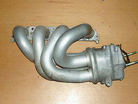
Have never seen a plenum attached this way, don't know enough to say why not. Would like to discuss this design.

In my oppinion this will provide adjustability to plenum volume as well as runner lenth (plenum might bey made up of two parts, one sliding over another, as well as runners being made same way on the part that attaches to the plenum). Also due to the flow-through design, the air would be getting into runners alot easier since it does not have to make a 90 degree turn like in conventional desigs.

Would like your oppinions about it.
 
Last edited:
Wouldnt that place the plenum right on the battery and the throttlebody/IC piping on the strut tower?
Reminds me of an exhaust manni.
 
Wouldnt that place the plenum right on the battery and the throttlebody/IC piping on the strut tower?
Reminds me of an exhaust manni.

It would, but this is just a rough draft that can be tweaked and moved around some. I got inspired to do this after looking at some exhaust headers, that's probably why.
 
What exactly are you talking about?

EDIT: Oh, never mind. I see what part you are talking about. Still, it's inside a smooth pipe, not trying to go over an edge like in stock intakes?

Sorry not trying to bash it just my opinion. Would you use this on a naturaly aspirated motor? As opposed to the "header" manifold sees vacuum, so I dont see how it can benefit fron a "smotther" pipe.
 
Sorry not trying to bash it just my opinion. Would you use this on a naturaly aspirated motor? As opposed to the "header" manifold sees vacuum, so I dont see how it can benefit fron a "smotther" pipe.

It's ok, Kid. I want some critisism so to know what needs improvement :thumb:

This was planned for a non-turbo motor. Please explain the "manifold sees vacuum" part. Did you mean "uses vacuum"?
 
That type of manifold would be beneficial for low end torque. The long runners and sweeping bends will give the air lots of velocity but in the higher rpms will choke out. That manifold looks a lot like a late 90s toyota 1.8l intake.
 

Attachments

  • 1.8l toyota.JPG
    1.8l toyota.JPG
    22.6 KB · Views: 575
If such a design were to be engineered for a turbo engine, I think it'd fail since shorter runners are better. Still not bad bad for thinking outside the box to develop something new.
 
TurboAnything, thanks for the picture, had no idea something similar was built. Where's the plenum on that thing? Does it bolt on to this header?
Spyderdrifter, the runners in the design are approximatly 12" long (when measuring center line of each runner). That's the same as stock n/t ones, tuned for lower end torque, about 6000 RPM peak.

Any advice on plenum volume? And how it affects engine perfomance?
 
GM also used a similar intake manifold on their Quad-4 engine from the late 80s to the early 90s. Don't think it is gonna work to well without a lot of modding. May be worth looking into though. If the runner spacing is close enough you might be able to cut the GM flange off and have a DSM flange welded on. Just a thought.

You must be logged in to view this image or video.
 
Support Vendors who Support the DSM Community
Boosted Fabrication ECM Tuning ExtremePSI Fuel Injector Clinic Innovation Products Jacks Transmissions JNZ Tuning Kiggly Racing Morrison Fabrications MyMitsubishiStore.com RixRacing RockAuto RTM Racing STM Tuned

Latest posts

Build Thread Updates

Vendor Updates

Latest Classifieds

Back
Top