The Top DSM Community on the Web

For 1990-1999 Mitsubishi Eclipse, Eagle Talon, Plymouth Laser, and Galant VR-4 Owners. Log in to remove most ads.

Please Support Fuel Injector Clinic
Please Support Rix Racing

1993 1G TSi

This site may earn a commission from merchant
affiliate links, including eBay, Amazon, and others.

This site may earn a commission from merchant affiliate links, including eBay, Amazon, and others.

Ludejim

10+ Year Contributor
63
10
Apr 28, 2010
Centennial, Colorado
This is my first attempt at anything of this magnitude. I have done smaller projects on cars and motorcycles, but until now, I had never pulled a motor or done anything that I am about to show you. Also note that the order in which I present these modifications does not represent the actual order in which they were completed, although I did try and present them in a manageable order.

Contents:
At anytime, you can press control + F in the browser window and search for each of these terms. It will take you to the beginning of that part of the project.

  1. Motor Failure
  2. Throttle Body
  3. Motor Mounts
  4. Turbo, exhaust manifold, intake manifold
  5. Putting the motor in
  6. Clutch & Transmission
  7. Parts Delivery
  8. External Oil Cooler
  9. Battery Relocation
  10. VRSF FMIC Install
  11. WasteGate
  12. MAP Sensor, AFPR, and Partial wire tuck
  13. PCV valve and oil pressure sending units
  14. Looping lines
  15. Cold Air Intake
  16. Gauges
  17. Fuel Pump Rewire

Motor Failure

I got my 1993 1G TSi 7-bolt about a year and a half ago, it ran great and I loved it. I got ECMLink V3, a wideband O2, and changed the intake on the car to speed density. This being my first turbo car I really neglected the oil. With a few oil leaks around the oil pan, the turbo oil feed leaking, and numerous other things that I had no idea about, it does not surprise me that the engine failed due to lack of oil. It was definitely my fault, I have come to terms with that and I am ready to rebuild my car and take care of it properly. Sorry if there are pictures missing here or there. Here are some pictures of the engine pull:
2012-05-03114809_zps9537f232.jpg


Valve cover, exhaust manifold, turbo, throttle body, and most of the electrical/vacuum/coolant lines removed.
2012-05-04122623_zpsfa8a2fb2.jpg


Engine out!

Head removed. Camshafts, valves, springs, retainers, and seals are all gone. At this point you can also see the crank in the background along with the girdle. No damage was done to the head which makes me happy ?

This, on the other hand, does not make me very happy. Nearly every bearing was shot.
DSC00289_zps6a59bc82.jpg

The thrust bearing is really bad.
DSC00302_zpsc4826d68.jpg


Crank discoloration.
DSC00283_zps584315f6.jpg


This is where the crank was walking into the block.


At this point I knew what had happened, and I just needed someone who could help me out. I do not build engines and I do not have the correct tools nor the knowledge. I jumped on my motorcycle and took a trip down to Jacks Transmissions in Colorado Springs. Turns out I chose the wrong day.
2012-06-02135350_zps6c25f26e.jpg


About 15 minutes away from Jacks, I got hit by a huge thunderstorm. I pulled over into the gas station and waited it out. Took about 30 minutes and then I was back on the road to Jacks. I talked to Jack for probably an hour and a half. Picking his brain on what could be done to my motor. We decided that using my block and crank was a bad idea because the crank had heat stress and discoloration and the block had wear marks from the crank walking. Jack set out to build me a 6-bolt block with 2G pistons, 1G rods, and the thrust bearing out of the later model 4G63s. There is nothing super special about the bottom end, except for the fact that it is new. From here it was a waiting game, and I knew it was going to be a while before I got my engine back.

Throttle Body
I apologize that I do not have before pictures, but rest assured, the throttle body was nasty.
Here is a list of things done to the throttle body
1. New ISC Motor
2. New O-ring seals
3. Vacuum lines looped
4. FIAV Bypass plate (Not in picture)
5. Plugged FIAV coolant lines (not in picture)
6. Polished throttle plate and cleaned surfaces
DSC00177_zpsa013ed83.jpg


DSC00180_zps7a2a3156.jpg


Motor Mounts

I had the front and rear motor mounts welded up with 3/16” steel plates.
2012-10-23155014_zps62a9388e.jpg


The left and right side were treated to new Prothane motor mount inserts. I do not have separate pictures of these. I did have to pay to get the old inserts pressed out. You can see the new Prothane mounts later down in pictures of the motor install.

Turbo, exhaust manifold, intake manifold

I got a call from Jacks Transmission telling me that my motor was finished. So I drove down to Colorado Springs to pick it up. I took my head, valves, cams, springs, lifters, and retainers down to Jack so that he could put them on the new block.
2012-10-04175534_zps06b3e0c7.jpg


2012-10-04175525_zpse4cb547e.jpg


I placed an order for an FP exhaust manifold.
2012-11-04202925_zps523de67e.jpg


A new BEP housing.
2012-11-10173533_zpsd70455ae.jpg


And an hx-35 CHRA and compressor housing.
2012-11-10173508_zps6a96455e.jpg


The turbo, BEP housing, FP manifold, and stock intake manifold bolted up. The intake manifold was cleaned at Heads by Drew. Also you can see my oil feed line for my turbo coming from the 1990 OFH.
2012-11-15203919_zpsa6460e61.jpg


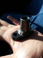
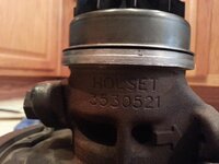
My oil return line consists of a stock holset return line flange with about 1” of 19mm I.D. tubing connected to a ¾” I.D. silicone hose that connects to a stock 2g oil return line that has been cut down just a little.
DSC00330_zpse1eb05b2.jpg


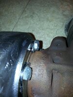
I changed my turbo water pipe to the none turbo pipe because the hx-35 is oil cooled only. My compressor cover just barely touched my water pipe.
DSC00326_zps1ab40f0ecop_zpsf3842e30.jpg
 
Last edited:
Putting the motor in
Before putting the motor in, a lot of clean up happened, which I only have one photo of. I pulled all of the material off of the firewall, removed the ABS system, installed non-abs brake lines, removed the cruise control, removed the power steering, and removed the air conditioning. I also removed the wiring harness from the firewall. At this point I was feeling really dirty, so both the engine bay and I got a thorough cleaning. After the bay was clean, I reposition the wiring harness so that it would be out of view for the most part. I also chopped the long part off of the driver’s side motor mount to clean up the appearance.
2012-11-08191618_zps023d77f0.jpg


After all of this, I put the motor in the bay.
2012-11-18170516_zpse81d5238.jpg


Clutch & Transmission
After the motor was in I put on the flywheel
2012-10-29173938_zps1e6b6160.jpg


I cut a piece of ¼ in steel and drilled two holes in either end. This allowed me to hold the crank in place to torque down the flywheel bolts.
DSC00342_zps4ffcad69.jpg


Next went the clutch disk with the alignment tool all lubed up
2012-11-20191741_zps8b740e71.jpg


And finally the pressure plate which was evenly torqued down.
2012-11-20195218_zps702927cf.jpg


Finally the transmission can be mated to the block.
2012-11-23202447_zpsf7bc227a.jpg


I needed to repair a broken CV boot.
2012-11-21200258_zps69e65750.jpg


2012-11-22090614_zpsbb76e2f9.jpg


After fixing the CV boot I replaced the axle seals on the transmission and reinstalled the axles. Then the transfer case needed to be reinstalled along with the rear drive shaft. This was a pain, but I managed to get it all back together.
Parts Delivery
A few packages from extremepsi arrived.
This one has the oil cooler, fittings, FP intake pipe, O2 housing gasket, oil feed line, turbo timer harness, O2 bung, and other miscellaneous items.
2012-11-08172547_zpsbc489c28.jpg


This one has my 4” CAI pipe, Hallman boost controller, waste gate flanges, fuel injectors, couplers, cam cover, and other misc. stuff.
2012-11-29172431_zpsf763e65d.jpg


Oh yea, and my new wastegate!
2012-11-29172602_zps78baade0.jpg


External Oil Cooler
For this I went to home depot and picked up a 2” x 1/8” x 8’ long piece of aluminum. I planned on getting a long section to build brackets for the oil cooler and other things in the engine bay that needed to be mounted.
I bent some brackets and drilled some holes in it to mount my oil cooler. The previous owner of the vehicle had fog lights installed. I removed these to give air flow to both sides of the bumper. This feeds the oil cooler with fresh air.
2012-11-29214230_zps7f398b92.jpg


2012-11-29214127_zps4d17460e.jpg


Battery Relocation
I took the short route on this one, I decided to just lower the battery. I created a new strap out of my aluminum that I purchased. This holds the battery down far better than I ever imagined. It also gave me all kinds of room to work with. To do this you have to remove your battery tray and charcoal canister and essentially the rest of your vacuum system.
2012-12-03185350_zps5c828b2b.jpg


2012-12-03190407_zps4e64793f.jpg
 
VRSF FMIC Install

This was kind of a pain. If you take the correct steps and pay attention to what you are doing, it is not that bad. I removed my front bumper and crash bar. Then I lined my intercooler up to the frame of the car. After I got a fairly good idea of where the intercooler pipes needed to fit, I started to cut with the angle grinder and cutoff wheel. After I was done, I sprayed undercarriage coating over the raw metal to protect from rust. I also followed up with some vacuum hose and silicone to cover the raw cut. Take a look at the pictures below and you will get a good idea of what I mean. This helps protect the intercooler from metal wearing through metal. I also had to clip part of the radiator flashing to get the proper fitment. Like most of us, I also cut the crash bar to fit around the new intercooler.
Raw cut with grinder and a coat of under spray on the passenger side
2012-12-09142252-1_zpsa66f340d.jpg


This is the driver’s side with the vacuum hose in place over the raw cut metal.
2012-12-09163001_zpse8d28949.jpg


Front view of the intercooler installed
2012-12-06203920_zpsd1d99309.jpg


Clearance in-between the crash bar and the FMIC
2012-12-10181251_zpsd3b7950b.jpg


Intercooler piping all finished up. I had to order a 2.5” to 2.5” 90 degree coupler for the compressor to lower intercooler piping. The VRSF kit comes with a 2” to 2.5” for the stock compressor housing. In these pictures that fitting is just kind of plumbed into the pipe directly in front of the exhaust manifold.
2012-12-11174249_zps538180ee.jpg


2012-12-11174357_zps5754b42e.jpg

WasteGate
This is an O2 dump from my previous setup. It had an internal gate.
2012-12-17175830_zps8e354c81.jpg


I spent about two hours rough fitting and cutting down the pieces of that dump tube and then took it to my welder to complete the transformation.
2012-12-18150239_zps2623f977.jpg


This didn’t cost a whole lot of money, so I am not overly concerned about looks. This is after 1800 degree paint was applied.
2012-12-18203834_zpsd96a0977.jpg


Test Fitting
2012-12-23153142_zpsadae7ded.jpg


The waste gate turned out to be really close to the alternator and the O2 sensor. Hopefully this will all function properly.
2012-12-23201146_zps1cf18e4d.jpg


MAP Sensor, AFPR, and Partial wire tuck

This photo shows the MAP sensor and AFPR installed. I used more of my aluminum strap to build the mount for the AFPR. Also the injector wiring harness, and all the wires for the CAS, TPS, Coolant temp sensor, and other wires go in between the C shape of the intake manifold. The new throttle cable is also in place. It has been wrapped underneath the intake manifold. While under there I also connected the knock sensor wiring, wide band O2 and its wiring, brake booster vacuum line, and the ground for intake manifold. Air intake temperate sensor was tapped into the intake manifold. This was also done at Heads by Drew. If you are curious as to the location of my map sensor, that location is the shortest route to a vacuum port on the intake manifold. The actual line connecting the MAP sensor and to the intake manifold is maybe 1 ½”.
2012-12-23202211_zpsfc13652a.jpg


The AFPR line goes right across the top of the clutch reservoir. I don’t really like this, so it may change once I bleed my clutch. Also my bracket is cut at a slant, I would like that to be straight.
2012-12-04205757_zps8d215eac.jpg


View from underneath the car for the oil temperature sending unit and the wide band O2 Location. This image also shows that I have reinstalled the member that goes under the transmission.
2012-12-23115514withlabel_zpsa77c233f.jpg


PCV valve and oil pressure sending units

Here is my autometer electronic oil pressure sending unit hooked up in the stock location with the autometer adapter.
2013-01-04224218_zpsd95d7132.jpg


These are the PCV hoses that run to the catch can. They are actually routed differently now. Mainly the one blocking the fuel feed is now going in between the C part of the intake manifold. I may as well squeeze in the fact that the fuel feed is also upgraded to -8 AN line with a new filter.
2013-01-06180156_zpscd18b30e.jpg


Here is the oil catch can for the PCV valve. I used more of the aluminum to bolt this catch can onto the battery tie down. This way the fluid in the can is always at its lowest point. Also, unseen here is a one way valve that is in between the line that goes from the catch can to the intake manifold. This is later shown in the diagram of all the vacuum lines.
2013-01-06180143_zps6d68b87e.jpg
 
Looping lines

This looped line is for the oil coolant line running to and from the stock turbo.
2013-01-06180005_zpsdbeebd68.jpg


I also looped the lines that used to run to the throttle body for the FIAV. You can also see the EGR valve block off plate in the right portion of this photo as well.
2013-01-06180038edited_zps9bf72502.jpg


Another line that I looped was my power steering line. Since the pump for the power steering is removed, I have no use for all the lines. Unfortunately I do not have pictures of this. I can say that I want to switch to the 1.8L manual steering rack as soon as possible.
Cold Air Intake
Here is the intake tube dipping down where the old side mount intercooler used to be. You can see that I have enlarged the hole so that a 4” pipe can fit through it. Then I sprayed with my under carriage paint again and wrapped it in some more vacuum line. The quarter is in there so that you can reference the size of the intake.
2012-12-16192510_zps5c3fe312.jpg


And from the front you can see the filter stick out where the side mount intercooler used to get its flow of air.
2012-12-16192725_zps5234e200.jpg


Gauges


You have seen that I have installed the sending units for most of my gauges. Here, on the a-pillar I have my engine oil pressure, engine oil temp, and turbo oil pressure.
2012-12-15172723_zps45aa0183.jpg


Some other photos from the install.
2012-12-16145715_zps5674d694.jpg


2012-12-16175803_zps7786bd99.jpg


This is the fuse block that I use for the gauges. You can NOT see the bottom portion where my +12V wires are connected. That means those top three open prongs are available for more devices. I need to cap those off.
2012-12-16190427_zps83936624.jpg


And the gauges installed in the car.
2012-12-16190811_zps743dc1ab.jpg


This is my turbo oil feed line. This line is after my oil restrictor and right before the turbo.
2012-12-23145722_zpscf7c1ea0.jpg


Here is the layout that I used to wire my gauges.
GaugeWiring_zpsf935ed54.png


Before I destroyed the motor I had already installed the gauge for the wideband O2 sensor and the boost gauge. I got a replacement matching boost gauge that just needs to replace my old one.

This is kind of random, but I felt worth showing. This is a diagram of essentially all of my vacuum lines except for the boost gauge, and brake booster.
vacuumsetup_zps7585efd3.png


Fuel Pump Rewire
I do not have pictures of this process, although, I can provide a link to a kit that is identical to mine. The only difference between the one linked and the one that I have is the price. Ebay fuel pump rewire kit.

I am currently working on finishing this project. My goal is to have it running by next week. I will post photos of my progress. I do have the blow off valve connected, although I am not sure if it is correct. I also got new radiator hoses and new heater core hoses. I also did new plugs and wires. Boost leak tested from the throttle body elbow up to 20, then the home depot BLT popped off. So I sanded the PVC pipe, put rtv on it, and then put the coupler on. I let it set over night and then tested again. This time it didn't pop off at 20, but I fixed a bunch of leaks. I can't really test from the turbo compressor because it leaks through the bearing. There is no oil in it.
 
Last edited:
^^Thanks! Its coming along.

So it's the middle of the week and I find myself scrambling to get things together for the nice weather.

I was having trouble sourcing a hose that was flexible enough to suite my BOV re-circulation needs. I stumbled across this arcticle. It seemed to be the perfect solution.

This is a picture of the hose mocked up.
2013-01-15201633_zps24382adb.jpg


I'm going to try to paint it and put it on. Right now my FP intake pipe is having a fitting welded on for the crank case breather.

This is a picture of my pcv setup per Calans instructions
2013-01-15194435_zpsfc52b539.jpg


Test fitting the system to see where I need to weld the intake pipe
2013-01-15194802_zps3c9fc0df.jpg


I will post final pictures of how that comes out with new welded intake pipe and the BOV re-circulation hose clamped into place with paint on it. Hopefully that will hold up.
 
Last edited by a moderator:
Why are you recirculating the bov if you are running speed density?
 
If I am not mistaken it should help with turbo spool in between shifts. The intake pipe is being charged with air from the BOV when it discharges. In a system that is functioning properly the BOV will open during a shift so that compressor surge does not happen. Also, I believe that even though speed density is not affected as much by a vented BOV, I do believe that recirculating the air is a good idea. The more air available, the better right? Does this just come down to whether or not you want a really loud pssshhhhh noise?

edit:

Here is some more info and opinion
BOV shifts
Other peoples results

There are so many threads about venting to atmosphere and recirculating it's ridiculous. Although you are correct I could let it vent to atmosphere with speed density.

Here is how the BOV recirc came out:
2013-01-17202959_zps1a6a0db9.jpg


And the welded FP intake pipe, which I will probably have painted later:
2013-01-17203112_zps39951854.jpg


Leading up to the rest of the crankcase ventilation:
2013-01-17203137_zps010baeb4.jpg


The engine bay nearly complete, the most that has to be done is cleanup work:
2013-01-17202922_zpsedfe545b.jpg


I also replaced the fluids in the transmission, transfer case, and rear differential and Installed new fuses.

Well, I have yet to start the car and the week is almost over. I have a lot of things to do for work, and family this Friday and Saturday. So, Sunday will be the day for getting the car started. Here is list of EVERYTHING that I have left to do before I start the car:

  1. Put tires on - Done
  2. Calibrate wideband O2 and then tighten into bung - Done
  3. Remove old gas - Done
  4. Boost Leak Test - Done
  5. Prime the motor to be started - Done
  6. Get a fire extinguisher - Done
  7. Connect battery - Done
  8. EGR Temp Input (ECU Pin 15) - wideband O2 and - Donemodel
  9. Resolder front o2 wire to front o2 ecu wire (from my previous setup) - Done
  10. Fabricate an enclosure to prevent water from entering intake
  11. Put in break in engine oil - Done
  12. Put in coolant - Done
  13. Configure ECMLink
 
Last edited by a moderator:
I finished a lot on that list yesterday. For anyone who cares, I think think the best way to drain your gas is from your fuel feed line. If you have Link, you can just use the fuel pump to drain your gas tank. I timed it at around 5 gallons in 5 minutes. This equates to a Gallon a minute. Convert that to liters and I get 3.78541 multiply that by 60 and you get roughly 227 LPH. Hopefully that will work out.

Anyways, I didn't get to start the motor. I drilled out my restrictor for my turbo to .075". This means I had to take apart the oil feed at the oil filter housing. As I was putting it back together, I managed to not only cross thread the male fitting, but also crack the fitting:

2013-01-20163841_zps6677609e.jpg


I am going to try and get a replacement today.

So here is the fitting that I came up with. My machinist really helped me out here. He threaded the inside of this 4 an fitting and then created a brass restrictor that he then threaded into the 4 an fitting. The fitting and machine work cost me $25.00

IMAG0532_zpsfb85fbe0.jpg
 
Last edited by a moderator:
Looks great!! This is really something I can't wait to do one day!!
 
looking good man. If you ever need a hand im right over at buckly and smoky hill.

Awesome, that is very close to where I live. I am off of Havana and Parker. Good to know. Maybe I will swing by when this thing is running. Are you any good with VE table adjustments? I remember how long that took me to adjust when I first got speed density.

Looks great!! This is really something I can't wait to do one day!!
Thanks man. It takes a lot of patience I can tell you that. It has definitely tested my anger management skills.
 
So my turbo is toast. I heard a howling that turned into crunching at certain rpms. Once I was out of vacuum and into boost, everything seemed to operate normal. The BOV would open when I would let off of the throttle, and there didn't seem to be any compressor surge. Boost held roughly 13 PSI. I supposedly have a 1 bar spring (14.5 psi). I think I have a loss of pressure from the compressor housing to the throttle body. I would imagine it is the FMIC. My boost gauge and MAP sensor are hooked up to the throttle body. If I were to put the boost gauge on the compressor housing I would probably see something around 14.5 psi.

The break in seemed to go well. I have a compression tester that I will use while priming the new turbo with oil. Oh yea, forgot I found a holset for $100.

Here is one picture of the old compressor wheel. It doesn't look too bad, but some fins are a little bent and the shaft play is horrible. I have yet to see the turbine wheel because I need to mock up a new return line. The one that I had originally on there is leaking.
2013-01-25131606_zps0480a11d.jpg


I also have very small leaks around the oil filter housing. There are so many connections, I need to use a high temp sealant on all the threads to ensure I don't leak any oil. The oil cooler lines and the turbo feed line consist of many fittings, about 10, and each one has to be perfect.

I will post some pictures of the new turbo when I get it. Hopefully this all works out well.

Ok here is the new turbo, I got it for $100. Very little up and down shaft play. Once again I imagine the journals are dry. What is the best way to prime that turbo?
2013-01-30223754_zpse220ef40.jpg


My oil return line was leaking for some reason during the initial break-in. I cut the stock hx35 return line and had a 2" straight section welded onto the flange at a slight angle. This will hopefully prevent the return line and the silicon hose from contacting the compressor housing and front motor mount.
2013-02-01155047_zpsfe0671aa.jpg


I am also relocating my heater controls, this will allow me to put my AFR and boost gauge in the heater controls stock location. Right now both of those gauges are located behind the steering wheel on either side of the steering column, this doesn't allow viewing at very good angles. You can see those two gauges in the picture, ROFL that old crappy boost gauge is about to get upgraded. I eliminated the air source selection knob. I still need to paint it, looks like crap but functions and because race car.:hellyeah:

2013-01-30221950_zps5356938a.jpg


I will post some pictures of the dash when I am done with it. After that I need to take off my oil filter housing and port the relief valve. The balance shafts have been eliminated so that could be the cause. I also need to push my alternator down a little so that the waste-gate clears it. Hopefully they have the right sized belt for me.
 
Last edited by a moderator:
So in the last couple weeks I have pushed my alternator down about a 1/2", and it seem s to work just fine.

I also had my holset return line re-welded, It had a crack in it.

2013-02-08110853_zps1756663d.jpg


I also bolted up the BEP housing to the new Holset:

Rust removed
2013-02-03122425_zpsd589e9c9.jpg


Bolted up
2013-02-03114003_zps4e3ae777.jpg


I also completed the gauges in the middle dash
2013-02-02155325_zps75bb28b3.jpg


Black one is LC1 wideband
2013-02-02155247_zps64406114.jpg


And I plan on putting an EGT sensor in the empty slot.

I also ended up taking off the OFH because of the oil issues. Upon first inspection I found that the plunger part of the relief system was stuck shut. I took it apart, cleaned it, ported it, and put it back together. After this I also increased the size of my Holset restrictor to .093", which I think is rather large, but it keeps idle pressure at about 10 psi at 1000K rpm idle. I do not like having that high of an idle, but if it gives the Holset what it needs, then so be it.

Currently trying to get a solid tune. I think that my battery is giving me issues. If I am idling and rev the motor, the rpms increase and then decrease and it returns to a nice idle state. When I put it in first gear drive down the road, put it in neutral while rolling it will die. During this time, I can hear my alternator belt squeal and in my logs the voltage drops, plus the battery is old.
 

Attachments

  • 2013-02-08110853_zps1756663d.jpg
    2013-02-08110853_zps1756663d.jpg
    55.4 KB · Views: 40
  • 2013-02-03122425_zpsd589e9c9.jpg
    2013-02-03122425_zpsd589e9c9.jpg
    76 KB · Views: 37
  • 2013-02-03114003_zps4e3ae777.jpg
    2013-02-03114003_zps4e3ae777.jpg
    92.8 KB · Views: 37
  • 2013-02-02155247_zps64406114.jpg
    2013-02-02155247_zps64406114.jpg
    71.3 KB · Views: 33
  • 2013-02-02155325_zps75bb28b3.jpg
    2013-02-02155325_zps75bb28b3.jpg
    76.4 KB · Views: 37
Ok, i havent updated this is a while, and a lot of things have gone wrong. Firstly, looped power steering lines started to leak, so 2 worm clamps later and it seems to be better. Next is re-torquing bolts, I have thought about this so many times, bet have never actually got to doing it. I was under my car checking everything out, when I noticed that my transmission had some fluid on it. First thing I checked was the fluid fill bolt, and it was completely loose. Today I am going to go over every bolt that can reach without disassembling anything because that was bad news waiting to happen. The biggest problem that I still have is sealing that damn holset oil return line. I have got every other leak under control, but this return line is such a pain in the ass. I have redone it 7 times now. That's draining my oil 7 times. That's cleaning all mating surfaces 7 times. That's tracing and cutting gaskets 7 times. After 7 times trying different little tweaks to the assembly each time i got it to a very slow drip, like one drip every time I take it out to drive. That is unacceptable to me. This time around I am going the "lazy route" and using RTV for everything. No new copper crush washers, no doubling up the gasket, no copper spray, just RTV acting as my gasket, RTV in the threads of the bolts, and RTV caked around the flange at the oil pan. So if this doesn't work then I am dropping the oil pan and welding a 17mm pipe to the pan so that I can just attach a silicone hose directly to the pan. I also have this heat shield being sent by steve93talon along with this manifold blanket. I also ordered some DEI 2"x50' heat wrap for the down pipe. I am experiencing higher IATs so hopefully these items will help combat the engine bay temps in turn lowering my IATs. I will post some pictures as soon as everything is put back together.

Ok, i got the parts listed above and put everything on, looks pretty good to me!

Heat shield covering the new exhaust blanket:
20130721_200932_zps9a09278e.jpg


Heat wrap on the down pipe:
20130717_205310_zpsf2ca705f.jpg


20130717_205242_zps2a5689cf.jpg


After all of this I seemed to only see about a 5-10 degree drop in IAT temps. Thats not enough for me. On a hot day before all of this I was at about 135 degrees IAT and not im at about ~127 degrees. So i started to try and think of more stuff I can throw at it. First was an actual turbo blanket which is on its way, and the second thing is my front bumper is blocking 3-4 fins on my intercooler.

20130722_141058_zps0988fd49.jpg


You can see the intercooler popping out the bottom of the bumper. I am still trying to find a solution for this as I do not want to hack up my bumper. I have also been debating getting a slim fan to fit where the stock ac fan used to be. Right now I am only running one fan, and while it seems to keep my coolant temp low, it is not helping flush the hot air out of my engine bay. So maybe a slim fan that constantly runs will help keep those engine bay temps to a minimum.

So my IAT was located in the intake manifold :nono:, and after moving it to the throttle body elbow I confirmed to myself that the IM was heat soaking the sensor. Now my IATs are at a respectable 80-90 degrees. :thumb:

After the IAT issues was fixed I started to drive the car on a more regular basis, this meant also driving it at night. I rarely drove the car after dusk, so I really never used the headlights. So one evening I was out late enough to actually flip the headlights on, and to my surprise dsmlink was reporting battery voltage as low as 12.5. This was strange because when the car started I was seeing a happy 14.2v. I determined that the alternator was getting too hot (my lower heat-shield is non-existent). I picked up the Jay Racing alternator relocation kit along with the 96-99 CS saturn alternator. Installation was pretty simple because my A/C was already removed, and I had previously installed a 12v switched fuse block for my gauges. That made the wiring super simple. Now, even after my car is fully warmed up and I have the headlights on, I am seeing 13.8v-14.0v.

Now back to tuning, my idle is still pretty outta whack. Take a look at my log that I have attached and let me know if you see anything.
 

Attachments

  • rewired new alt.elg
    406.4 KB · Views: 77
Last edited:
Support Vendors who Support the DSM Community
Boosted Fabrication ECM Tuning ExtremePSI Fuel Injector Clinic Innovation Products Jacks Transmissions JNZ Tuning Kiggly Racing Morrison Fabrications MyMitsubishiStore.com RixRacing RockAuto RTM Racing STM Tuned

Latest posts

Build Thread Updates

Vendor Updates

Latest Classifieds

Back
Top