The Central Hub for DSM Community and Information

For 1990-1999 Mitsubishi Eclipse, Eagle Talon, Plymouth Laser, and Galant VR-4 Owners. This is where the DSM platform history is documented and archived. Log in to help us in our mission, and to remove most ads from the browsing experience.

3c1IZyWl.jpg

1992 Talon Tsi AWD Re-habilitation

1992 Eagle Talon Tsi AWD

This site may earn a commission from merchant affiliate links, including eBay, Amazon, and others.

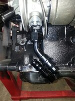
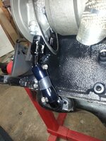
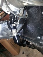
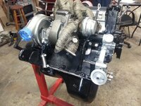
@911gdsmboostin I abandoned using the 1" hose, fittings are too big and won't work at the oil pan the way I'm doing it. They might work if I had a bung welded on, but I don't. 12an is the minimum spec for an hx35 i think, the equivalent of 19mm inside diameter. I'm not sure if its the same for an HX40 or not ?

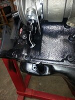
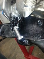
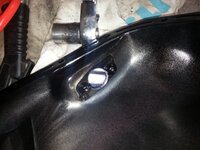
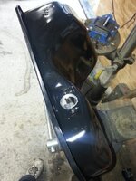
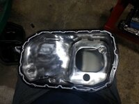
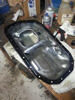
Remember that I drilled and tapped the oem oil drain hole, its just an experiment I'm doing. For a totally good way to do it my way, i'd have the fitting TIG welded inside the pan once I thread it in there. But welding may not be necessary for a leak-free setup.
 
I see, well what I have done is a lot of research being I am worrie about the story's of it need to be 19mm vs is doesn't what I hae come up with is that the hx35 and hx40 and I believe the hx52 all require a min 19mm inside diameter drain sorce as by oem spec but teirs a lot of argument about why can be used some people make with the equivelant of a -10 an and get away with it and some fail I haven't herd any real horror story's with a -12an which is 19mm I believe out side diam the -14 an is the equivelant of the oem drain at just over 19mm ID so what I'm basicly doing is looking for any feed back from ppl using differant set ups an opinions the best and closest I've seen besides totally customs drains is te -12 an and that's why when I came a cross a oil pan with the -12 an bung already welded on I snatched it up being I feel this set up might be okay any input you put up you can bet I'll be reading but if any info you come across with this let me know or post about is as I'm sure I'm not the only one wonderig
 
Holset does call for a 19mm drain on all the HX40 as well.

Here is a good thread that explains it in detail.

http://www.dsmtuners.com/threads/garrett-holset-turbo-users-your-oil-drain-may-be-too-small.331710/

what I hae come up with is that the hx35 and hx40 and I believe the hx52 all require a min 19mm inside diameter drain sorce as by oem spec

I haven't herd any real horror story's with a -12an which is 19mm I believe out side diam the -14 an is the equivelant of the oem drain at just over 19mm ID

To sum it up, AN hose sizes measure the inside diameter of the hose in 1/16 of an inch. 8 AN would be 8/16ths or 1/2 inside diameter so a 12 AN has an inside diameter of 12/16ths or 3/4 of an inch. 3/4 equals 19.050mm meeting the minimum requirement.

The idea is to make the drain as smooth of a transition as possible avoiding the use of 90 degree fittings if possible. Instead, use 30*, 45* and 60* fittings to accomplish this task.

 
@robertbaxley03 I still can't see what you did to modify your motor mount bracket. From the preview in the video, which is a great shot of it, one would assume you didn't touch it at all! :D

My other -12 fittings should be in the mailbox right now, so I'll go grab them and do some tinkering and take pics.
 
@robertbaxley03 damn, you chopped that whole thing off! I find it funny how similar we are in our builds/styles. Well, the fittings came, and it just seems that with my setup, the 90 at the bottom, while not optimal, is what I'll be using.

Here's a pic of a 45 off the turbo with a 90 on the oil pan:
rhcikNtl.jpg


Even if barbs are cut off, it'll still be too long, so I went full retard and cut the fittings where the tube part meets the barb structure:
zu6myAJl.jpg


I did a test-final fitment using the hose finishers I had previously ordered:

IhvUQacl.jpg


After further playing around, these "hose finishers" should not be used to clamp the hoses down, they're just crappy clamps, and heavier duty one's won't fit inside the finisher housings and allow the hose to also be pushed in there. So I cut the braided to length, got heavy duty hose clamps, and cut into my motor mount bracket some more. Here's what I think I'll call my finished product:
nOtVWEml.jpg


It really fits nicely, and its tight. So next up, I'll drill/tap the new oil pan I have, get my black and super grey rtv's, and finalize this portion of the build. With this done, I can move to timing belt and prepare to drop the motor back in the car.
 

Attachments

Last edited:
tmoney20g updated 1992 Eagle Talon Tsi AWD


View updates to this DSM profile...

Updated some mods that were TBD and I recently purchased, etc.

Also got back to work on the oil drain today. I was satisfied with yesterday's outcome, so today I drilled/tapped the new Spectre pan:

(Exterior)
SBBSdLwl.jpg


(Interior)
rMzisZLl.jpg


Cleaned up all the overspray that the oil pan comes with:

PbDgnTfl.jpg


You don't want that paint gumming up and ruining your brand new engine/oil pump!

Applied the 4mm bead of super grey:

vYMjmNQl.jpg


And install:

n7WOF2Ll.jpg


I have an idea to prime the motor of oil before putting the timing belt on. If you ever had nitro powered r/c planes, you might have had a starter for them. Its essentially a hand-held 12v motor with a little rubber cup on the end. You'd fire it up and push the cup to the prop of the plane to start it, instead of cutting up your fingers manually flipping the rotor around to start the engine. So next weekend I might try this out to prime the internals with really cheap oil, then drain it. See if any debris can get flushed out of the oil galleys and whatnot.
 

Attachments

Last edited:
You'll have it soon buddy. I hope they fix the picture linking soon too :) Makes threads like mine a little easier to browse.
 
01/10/15:
Its frikkin freezin mr bigglesworth! Still decided to do some hardware work on the engine. The 10-pack of stainless m8x1.25x100 studs came, so I test fitted them and found a nice length around 67mm to cut them to:
2oPelqVl.jpg


Also replaced the water outlet and cas studs so they all match. Remember that one of the cas studs, closest to the intake manifold, is longer to allow the engine hoist bracket between the head and throttle body, but I won't have that.... and for some reason, even tho this is a brand new oem head, 2 of the water outlet studs had screwed up threads, so rather than mess with them, they're all replaced, and loctited.

On both sides of the heat spacer is a felpro hi-perf intake manifold gasket:
7QmWngzl.jpg


Add the manifold itself(top):
R8BxG6ql.jpg


Manifold again (bottom):
9RUcnt4l.jpg


I threw on the Wilson TB, 2 m10x1.25x60mm stainless bolts (need another one for the manifold, NAPA only had 2). Also put my new hi-z FIC 1100s on my new Magnus fuel rail, installed that and the -6an end fittings, taped them all off, along with any other openings, and called it a day:

EhR4b62l.jpg


Oh yea, oh installed (4) 1/8npt plugs in the water outlet, and 2 of the senders, still need the top a/c cutoff switch and the rear water outlet hose connection, and i have to find where i put the new t-stat and 2 new bolts to put the tstat housing together all the way. JNZ has some stuff on order for me, so I'll just add those things to that order.
 
Last edited:
1/17/15:
Josh sent me some goodies, new black lower timing cover (we have the only black top timing cover shown in the system on order, hopefully that gets found and sent to me *fingers crossed*), timing cover bolt kit, water joint (for the t-stat housing to heater core), a/c stop switch (upper t-stat housing sensor), a 5 pack of female NMWP connectors, and the female maf connector, just in case I really botch the one up I have here.

So I finished up the t-stat housing and bolted her together:

Ro8DvW0l.jpg


FhGsO24l.jpg


And continued on my oil feed setup. First I installed the new gvr4 alternator I picked up last summer, then installed my purolator filter that i'll be using for break in, and test fitted the oil feed adapter again:

u2Kx2Dul.jpg


Then I grabbed the upper motor mount to be sure it would fit with the distribution block mounted:
dqlfGJ1l.jpg


After all is said and done, I'm very happy with the outcome. Justin shipped me a 90 for the oil feed inlet at the turbo, which kinda bends that line out in front a little too much, so if I can find that same fitting in a 45, I think I'm golden.

Then I'm ready to prime the oil system, and do the t-belt!
 
Here's the indoor fun I'm having:

dejaJye.jpg


I have to clean up the harness at the ecu connectors because Jim had the afc hardwired, so I'm removing those leads and straightening out the wires there. Also removing sensors I'll no longer need/be using, all the way back to the ecu harness, by unclipping the pins and removing the entire length of the circuit.

These include:
1. Power steering oil pressure switch (#5 on C66)
2. Idle Switch (#14 on C66)
3. EGR temp sensor (CA Only) (#15 on C66, which mine did have)
4. EGR Control Solenoid Valve (CA) (#53 on C65, which mine did have)
5. Fuel Pressure Control Valve (#57 on C65)
6. Purge Control Solenoid Valve (#62 on C65)
7. Wastegate Solenoid (#105 on C64)

I'll also be shortening the maf wires, back to the firewall area, since I'll have the SD setup which will be pretty much at the firewall, so that's like 2' of wire removed, and that's 6 or so wires. Should clean up the bay nicely.
 
Just started pulling the dash so that I can get to my harness this weekend :) Look at all the joy I have ahead of me ROFL Looking good and can’t wait to see the finished product.
 
1/20/15:
On this edition of Fun with Wires, we make the ford TPS usable with the oem engine harness! Since I have the Wilson 75mm throttle body mounted to my FRH manifold, it needs a ford tps. I took the old tps off my 1g throttle body, and carefully cut away plastic until I saw the 3 metal tabs to which the wires used to go to. Then I soldered the wires from the ford tps to it:
PiC9jUcl.jpg


Seemed to be pretty strong, so I buttoned her up with some electrical tape for a finished product:
nl4zQMol.jpg


Then I took a look at my Speed-Density connector, it only uses 4 leads, whereas the stock MAF required 7 leads to operate. The photo shows the male end of the SD connector on the right, and corresponding rear of the 1g MAF connector:
HUSG0dKl.jpg


So it looks like it needs all 3 on the top row, #4 was already not a lead.
And instead of all 4 on the bottom row, it only needs the bottom left. So I went ahead and also removed those wires from the harness, or safed-off any leads that were interconnected to other things, like the fat red power wire.

Here's the ecu connector diagram I've been going off of:
W4iIDhu.jpg


All the leads with a Red X next to them have been removed from the harness. I put them all aside and labelled them, just in case:

sgURAv1.jpg


Now I'm shortening the remaining MAF leads about a foot, and I'll solder up the female connector to the wires.

Also ordered the SCG-1 today, so I'm close to finishing my wiring project. Also have to go grab my new alarm system and see what it requires, if anything from the ECU, for remote start, etc.
 
@o0GuitarKid0o what oil drainage thing ? the turbo oil drain ? turbo's aren't pressurized inside the CHRA. As soon as the oil leaves the fitting there's 0 psi, it gravity drains.

Picture your garden hose, for instance, with no spray nozzle, just the hose. Turn the hose on, water comes out the end. There's pressure INSIDE the hose, even 1mm inside the hose, but not at the outlet. As soon as the water hits free air, there's no more pressure.

So to the oil feed, there's oil pressure allllll the way up to the turbo oil inlet. As soon as the oil leaves that inlet fitting, zero pressure.

Now there could be an instance when your drain is too small, or you're flowing soooo much oil into the CHRA that it fills up, and the CHRA itself becomes one with the turbo oil inlet, at that point it'd be like holding your thumb over the garden hose, and pressure would increase inside the CHRA, which is how an oil seal can blow.
 
Hey tony i got mine on my desk too all tore out you gonna run it at the factory location or somewhere else, im thinking neary shift cable area.
 
Vic,
Factory location on the firewall for sure. Since I'll be doing a battery relocate to the trunk, I'm thinking of building a nice bracket above where the wires come thru the firewall, that would hide the wires. This bracket would be used for battery posts in the engine bay, and maybe hold my MAP sensors and boost control solenoid as well.

I don't think I can fully complete the wiring project until the motor is back in the car. That way I can map out where things will go the nicest.
 
This is a great build. What did you do to get the old bushings out of the front lower control arms? I practiced on an old set and didn't have any problem using a vice and a different siz sockets, but when I tried on the new ones I couldn't get the bushings to budge. The socket I was using slides right through the metal sleave so it's just the rubber not budging. Did you burn or drill it out?
 
@mbyoung424 I usually burn everything out then clean up the leftovers. I think that's the one I screwed up and cut out the sleeves when they were supposed to stay in. Luckily I had my oem fronts so I got the sleeves out of those and hammered them into these new control arms.
 
1/24/15:
Some of the parts for my COP came in... the coils and the jayracing plate. Still waiting on the leads, which did ship, but haven't arrived yet.

First you have to cut the bolts off that the coils come with:
8td0s7jl.jpg


Used my dremel with a cut-off wheel and gently got them off. Ran over to NAPA for some hardware, since it requires fasteners for the coil to plate, and the plate to valve cover.

You also have to trim the boots and springs. Without any trimming, here's how mine sat:
jd6fparl.jpg


Its about 20mm up, so I cut roughly 20mm of boot and spring. I wanted to have a little bump when you take it off, enough pressure that you can get a finger under the plate in order to remove it if you have to, you know, to swap plugs or whatever.

So here's the finished look:
tN5iqtFl.jpg


Hopefully everything's making good contact in there. Then decided to add the 4 qts of RotellaT 30w oil and a 1/2 qt of lucas:
aGpoq8hl.jpg
 
Last edited:
Add Value - Be Respectful - No Trolling - No Misinformation - Participate Often!
Support Vendors who Support the DSM Community

Latest Classifieds

  • For sale 2g 2G Mishimoto Radiator & Fan Shroud
    2G Mishimoto Radiator & Fan Shroud $200 + shipping and paypal feesYou must be registered to...
    • jersygsx
    • Updated:
    • Expires
  • For sale 2g 2G Power Window Switches ( tested and hardware included )
    2G Power Window Switches $55 + shipping and paypal fees* Tested 6/2/26 * Hardware included *...
    • jersygsx
    • Updated:
    • Expires
  • For sale VIRGIN 4G63 6-BOLT TURBO HEAD
    Came off a virgin stock AWD Auto 1G DMS (91), also have matching block and crank which are also...
    • The_Partout_Spot
    • Updated:
    • Expires
  • For sale 1G DSM 4G63 6-BOLT TIMING COVER
    Used, see condition in photos. Buyer covers shipping / fees.
    • The_Partout_Spot
    • Updated:
    • Expires
  • For sale Garage clean out
    Changing setups on the car and getting rid of some stuff as well that's been laying around. Will...
    • 92GSXtacy
    • Updated:
    • Expires
Back
Top