The Top DSM Community on the Web

For 1990-1999 Mitsubishi Eclipse, Eagle Talon, Plymouth Laser, and Galant VR-4 Owners. Log in to remove most ads.

Please Support ExtremePSI
Please Support STM Tuned

1G Erratic battery voltage?

This site may earn a commission from merchant
affiliate links, including eBay, Amazon, and others.

This site may earn a commission from merchant affiliate links, including eBay, Amazon, and others.

edged1g

15+ Year Contributor
302
25
Feb 23, 2005
Huntingdon Valley, Pennsylvania
In the attached log, battery voltage is acting strangely.

1. It is erratic all throughout the log.

2. At about 820 seconds, while letting the car idle, it starts acting like a square wave.

3. It drops as low as 12.0@850 RPMs at 472.093.

Doesn't seem to be correlated to anything. What could be causing this?
 

Attachments

  • log.2015.05.10-01.elg
    555.1 KB · Views: 74
maybe it dips low when fan=on, then goes back to 13.x when fan=off ?

fan is a pretty big draw, and it'd make sense to me, but i don't see your coolant temp really change at all in conjunction with the "square wave" as you put it.

also, why is your clutch switch always = 1 ?
 
Voltage regulator on the alternator could be going out.. mine would struggle to reach 13v, and then I didn't notice when it DID finally die, and was charging the battery at around 18v, which boiled it a bit. Thankfully the battery survived but still caused electrolyte to spill into the engine bay.
 
maybe it dips low when fan=on, then goes back to 13.x when fan=off ?

fan is a pretty big draw, and it'd make sense to me, but i don't see your coolant temp really change at all in conjunction with the "square wave" as you put it.

That was my assumption too after thinking about it. How can i correct this? They are aftermarket slim fans. Also worth noting, my battery is relocated to the trunk.

also, why is your clutch switch always = 1 ?

Because I don't have clutch cut enabled.
 
Voltage regulator on the alternator could be going out.. mine would struggle to reach 13v, and then I didn't notice when it DID finally die, and was charging the battery at around 18v, which boiled it a bit. Thankfully the battery survived but still caused electrolyte to spill into the engine bay.

It never goes above 13.6 volts in the entire log so i think its a drain as opposed to a regulation problem.

I'm just not sure how to find/fix it.
 
Neither did mine, for a couple years (<4k KM in that time LOL)
At first.
In fact, it struggled to even hit anything above 13 cold.


THEN the regulator went.

Just sayin'.
 
Neither did mine, for a couple years (<4k KM in that time LOL)
At first.
In fact, it struggled to even hit anything above 13 cold.


THEN the regulator went.

Just sayin'.

I don't have any logs of it cold so I'm not sure what the ECU was seeing for voltage. Been trying to figure out where the fan circuit gets power and ground to potentially upgrade or change it to a relay.
 
Been trying to figure out where the fan circuit gets power and ground to potentially upgrade or change it to a relay.
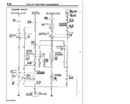
Here ya go:
 

Attachments

  • fans factory circuit 1g.jpg
    fans factory circuit 1g.jpg
    98.2 KB · Views: 76
Here ya go:

Thanks. I was looking at this in conjunction with this, pages 15 and 16.

http://www.lilevo.com/mirage/92-94 1G Talon Laser Vol 1 Electrical Service Manual .PDF/92-94EL.PDF

So in the picture you provided, it looks like the radiator fan motor is grounded to ground "3" which is near where the MAF is on a 1G(Pass side), and the AC fan and thermo switch are grounded to ground 2 on the driver's side. Do you agree?

I have 2 slim fans wired together on the radiator fan circuit. In this case, am I bypassing the "high/low change-over relay"? Could I be overloading this circuit? What would be the best way to remedy this?
 
Last edited:
Your "this" link doesn't work for me.

I don't have a 1g but from the grounds shown on p.8-4 of the DSM Backup Manual, yes that looks right.

If your slim fans are wired in parallel and positives connected to pin 1 of the radiator fan motor relay (negatives to ground), it will not overload that relay. The change over relay and condensor fan motor relay will then do nothing since no fan is now connected to them. This will work just fine. Just make sure the Thermo Sensor switch (which on a 1g is under the radiator) is still hooked up to pin 2 of radiator fan motor relay (and other side to ground) to turn the relay on and off. If you want the fans running whenever the key is On, just jumper the thermo sensor switch (or ground pin 2 of radiator fan motor relay).

I fixed the link.

Slime fans are wired in parallel as you stated. As for the relay, I don't think I'm overloading the relay per say, more the whole circuit in general, causing the voltage drop.
I don't want the fans on all the time. I want them to work like factory. Well, both work like the factory rad fan without the huge voltage drop. That's my goal.
 
Last edited:
If you want them both to work exactly like factory then wire the fans the way the factory has them - using all 3 relays. For less voltage drop use larger wires.

I want both fans to work exactly like the factory radiator fan. I don't have AC so I don't want anything to operate based on that. Do you think the factory wire gauge is inadequate for running both slim fans on the rad fan circuit?
 
Ok then just wire both fans as in my post 10 (which it sounds like you already have done judging from your post 11). The other 2 relays and circuitry won't be used. You'll only be using the radiator fan motor relay, thermo sensor, and your fans. Relay will handle the additional load. Existing wiring should handle additional current w/o significant voltage drop but to be sure, measure the voltage drop across the wire (from one end to the other, ie. relay to fan) when fans are on. Don't forget to also measure drop on the ground wire (ie. relay to ground). You can even measure what drop is across the relay contacts.

Or what I would do is first measure voltage across the fan and again across the battery for comparison both with fans on. Then across wires and relay contacts to find where the drops are and how much. If too much for you, add another wire in parallel to existing ones (or add a 2nd relay and wiring to the other fan which would be the best solution to minimize voltage drops and for fire hazard safety).
 
Last edited:
Support Vendors who Support the DSM Community
Boosted Fabrication ECM Tuning ExtremePSI Fuel Injector Clinic Innovation Products Jacks Transmissions JNZ Tuning Kiggly Racing Morrison Fabrications MyMitsubishiStore.com RixRacing RockAuto RTM Racing STM Tuned

Latest posts

Build Thread Updates

Vendor Updates

Latest Classifieds

Back
Top