The Top DSM Community on the Web

For 1990-1999 Mitsubishi Eclipse, Eagle Talon, Plymouth Laser, and Galant VR-4 Owners. Log in to remove most ads.

Please Support Morrison Fabrications
Please Support STM Tuned

1G The 1990 Engine COMPARTMENT Wiring Harness

This site may earn a commission from merchant
affiliate links, including eBay, Amazon, and others.

This site may earn a commission from merchant affiliate links, including eBay, Amazon, and others.

*****IMPORTANT*****
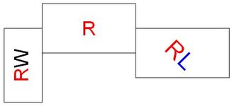
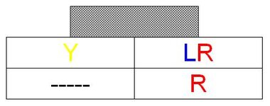
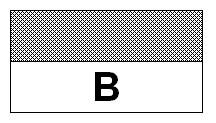
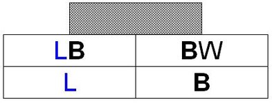
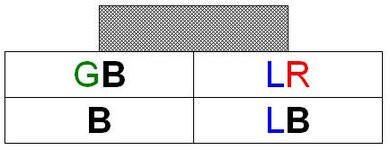
Note that the wire color layout diagrams accompanying each picture are as seen FROM the CONTROL HARNESS SIDE of the connector with the release tab (for a male side connector) or locking notch (for a female side connector) on top. That is, you are looking at the wires going into the connector, OPPOSITE the side that is pictured. Like this: How to identify ECU pin numbers.
*******************

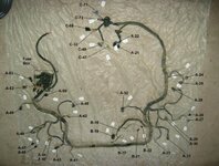
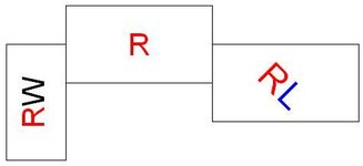
Consider this part two of The 1990 Engine Control Wiring Harness; this article covers the remaining electrical connections in the 1990 2.0L engine compartment as well as the handful of connectors that run to the interior on the driver side. For reference, the main diagram below is as viewed from the front of the vehicle; the long horizontal portion is the bit that runs underneath the radiator. This is my attempt to come full circle with the 2g Engine Bay Electrical Connections article posted by snowborder714 by providing visuals of each connector and hopefully aiding in identifying these connectors.

Each connector is given an alphanumeric identifier that follows the 1991 configuration diagram found in the electronic copy of the factory service manual: Download the 1G Service Manuals. For your convenience, these are pictured here.

You must be logged in to view this image or video.


You must be logged in to view this image or video.


You must be logged in to view this image or video.


You must be logged in to view this image or video.


Like the engine control harness, there are notable differences between this harness and those from later model years. Generally speaking, however, this article is relevant to all 1Ga (1990 and 1991, or those with pop-up headlights) models. On the other hand, the similarities and differences between this and the 1992+ harness(es) will not be covered now but may be added in the future; if anything, this will provide a reference for you to compare with your 1992+ harness to get an idea of what certain connections / connectors / plugs are. Now, without further ado, the complete engine compartment harness:
You must be logged in to view this image or video.

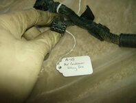
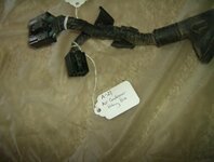
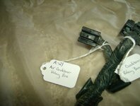
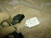
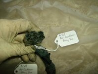
A-21: Air Conditioner Relay Box (black connector, small 6-pin)
A-21: Air Conditioner Relay Box (black connector, small 6-pin) /URL]
[URL="https://www.dsmtuners.com/threads/the-1990-engine-compartment-wiring-harness.473792/#post-153372381"] A-22: Air Conditioner Relay Box (black connector, large 6-pin)

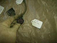
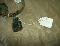
A-24: Windshield Washer Motor (black connector, 2-pin)
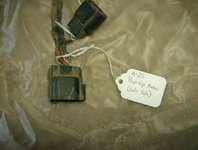
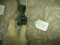
A-25: Pop-Up Motor Left Side (black connector, 2-pin)
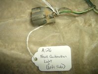
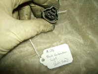
A-26: Front Combination Light Left Side (black connector, 2-pin)

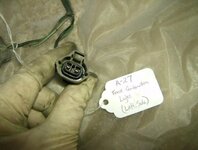
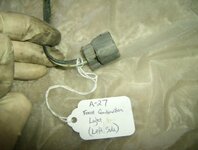
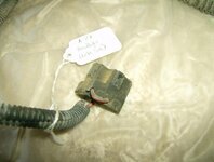
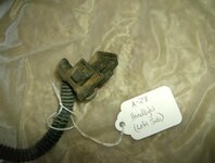
A-27: Front Combination Light Left side (black connector, 2-pin)
A-28: Headlight Left Side (black connector, weird 3-pin)
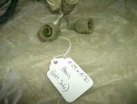
A-29 and A-30: Horn Left Side (slip sleeves, 1-pin ea.)
A-31: Fog Light Left Side (black connector, 2-pin)
A-32: Condenser Fan Motor for AC Circuit (black connector, square 4-pin)
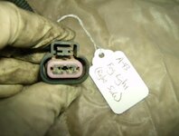
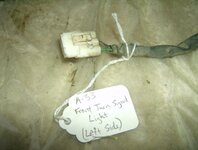
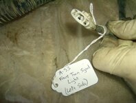
A-33: Front Turn Signal Light Left Side (white connector, straight 3-pin)
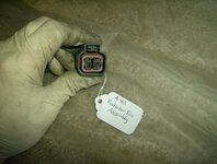
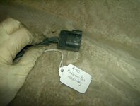
A-40: Radiator Fan Assembly (black connector, square 4-pin)
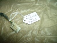
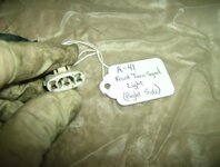
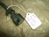
A-41: Front Turn Signal Light Right Side (white connector, straight 3-pin)
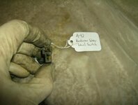
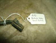
A-42: Radiator Water Level Switch (black connector, stacked 2-pin)
A-43: Fog Light Right Side (black connector, 2-pin)
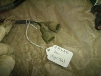
A-44 and A-45: Horn Right Side (slip sleeves, 1-pin ea.)
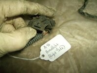
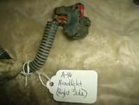
A-46: Headlight Right Side (black connector, weird 3-pin)
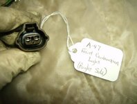
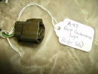
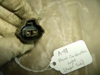
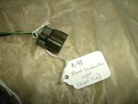
A-47: Front Combination Light Right Side (black connector, 2-pin)
A-48: Front Combination Light Right Side (black connector, 2-pin)
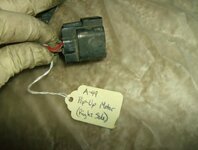
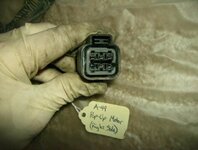
A-49: Pop-Up Motor Right Side (black connector, 2-pin)
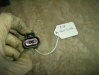
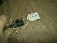
A-50: Hood Switch (black connector, 2-pin)
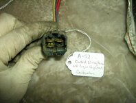
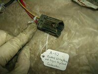
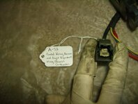
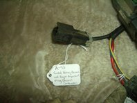
A-52: Engine Control Wiring Harness and Engine Compartment Wiring Harness Combination (black connector, wide rectangular 4-pin)
A-53: Engine Control Wiring Harness and Engine Compartment Wiring Harness Combination (black connector, large 1-pin)

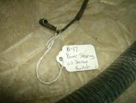
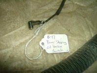
B-17: Power Steering Pressure Switch (brown L sleeve, small 1-pin)
B-18: Alternator (ring terminal)
B-19: Alternator (connector) (black connector, large 2-pin)
B-21: Oil Pressure Switch (dummy light) (black connector, small 1-pin)
B-22: Oil Pressure Gauge Unit (black connector, small 1-pin)

C-33: Diode (orange connector, straight 3-pin)
C-47: Engine Compartment Wiring Harness and Junction Block Combination (milk white connector, large 1-pin)
C-48: Engine Compartment Wiring Harness and Junction Block Combination (milk white connector, wide 8-pin)
C-68: Instrument Panel Wiring Harness and Engine Compartment Wiring Harness Combination (black connector, 10-pin)
C-71: Engine Compartment Wiring Harness and Body Wiring Harness Combination (milk white connector, wide rectangular 6-pin)
C-72: Engine Compartment Wiring Harness and Body Wiring Harness Combination (white connector, 14-pin)

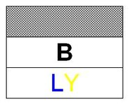
The wire color layout diagrams accompanying each picture list the original wire colors and individual wire locations are as seen FROM the HARNESS SIDE of the connector with the release tab (for a male side connector) or locking notch (for a female side connector) on top. They should be color coded correctly, but if there is a disagreement with the letters and the color of the letters, go by the letters. When two colors are listed together, the first is the main color and the second is the color of the stripe or tracer. The letters represent the following colors:

B - Black
W - White
R - Red
G - Green
L - Blue
Y - Yellow
O - Orange
Lg – Light Green

PM me if you find any errors and I will make corrections as necessary. Thanks to pauleyman for supplying the harness!
Note: There is some information that will be added in the future but this is a good base for any individuals who may need it.

Finally, the following supporting vendors supply the individual connectors linked or partial kits for different model year DSMs:
JNZ Tuning
Extreme PSI
Magnus Motorsports

At the end of the day, they are all coming from Sheridan Engineering.

EXTRA: Instead of creating another post, here's a list of the fuses in the Junction Block (J/B) (inside the cabin) by name and what number that corresponds to. These relate to factory wiring diagrams.
1 - Auto Seat Belt
2 - Empty
3 - Heater Relay
4 - Radio
5 - Cigar
6 - Door Locks
7 - 4 A/T
8 - Empty
9 - Wiper
10 - Head
11 - Gauge
12 - Turn
13 - Blank
14 - Anti-Theft
15 - Blank
16 - Heater
17 - Stop
18 - Back
19 - Room

You must be logged in to view this image or video.
[/URL]
 

Attachments

  • ConfigurationDiagram1.jpg
    ConfigurationDiagram1.jpg
    57.2 KB · Views: 526
Last edited:
A-21: Air Conditioner Relay Box (small, 6-pin connector)
 

Attachments

  • A-21.jpg
    A-21.jpg
    19.1 KB · Views: 346
  • A-21AirConditionerRelayBoxA.jpg
    A-21AirConditionerRelayBoxA.jpg
    33.9 KB · Views: 513
  • A-21AirConditionerRelayBoxB.jpg
    A-21AirConditionerRelayBoxB.jpg
    33.6 KB · Views: 384
  • A-21AirConditionerRelayBoxC.jpg
    A-21AirConditionerRelayBoxC.jpg
    36.4 KB · Views: 496
A-22: Air Conditioner Relay Box (large, 6-pin connector)

Connector available at: DSD06 F.
 

Attachments

  • A-22AirConditionerRelayBoxB.jpg
    A-22AirConditionerRelayBoxB.jpg
    33.5 KB · Views: 351
  • A-22.jpg
    A-22.jpg
    17.3 KB · Views: 1,065
  • A-22AirConditionerRelayBoxA2.jpg
    A-22AirConditionerRelayBoxA2.jpg
    35.2 KB · Views: 325
Last edited:

Attachments

  • A-24WasherMotorA.jpg
    A-24WasherMotorA.jpg
    33.6 KB · Views: 329
  • A-24.jpg
    A-24.jpg
    11.9 KB · Views: 1,113
  • A-24WasherMotorB.jpg
    A-24WasherMotorB.jpg
    37 KB · Views: 377
Last edited:
A-25: Pop-Up Motor Left Side

The pop-up motor harness connector is available at: NMWP 6P Female.

The mating connector for the pop-up motor is available at: NMWP 6P Male.
 

Attachments

  • A-25Pop-UpMotorLeftSideB.jpg
    A-25Pop-UpMotorLeftSideB.jpg
    38.5 KB · Views: 366
  • A-25Pop-UpMotorLeftSideA.jpg
    A-25Pop-UpMotorLeftSideA.jpg
    36.7 KB · Views: 431
  • A-25.jpg
    A-25.jpg
    16.9 KB · Views: 1,090
Last edited:
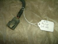
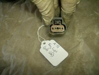
A-26: Front Combination Light Left Side
 

Attachments

  • A-26FrontCombinationLightLeftSideB.jpg
    A-26FrontCombinationLightLeftSideB.jpg
    47.5 KB · Views: 431
  • A-26.jpg
    A-26.jpg
    12.6 KB · Views: 1,063
  • A-26FrontCombinationLightLeftSideA.jpg
    A-26FrontCombinationLightLeftSideA.jpg
    42.3 KB · Views: 351
A-27: Front Combination Light Left Side
 

Attachments

  • A-27.jpg
    A-27.jpg
    12.2 KB · Views: 1,071
  • A-27FrontCombinationLightLeftSideA.jpg
    A-27FrontCombinationLightLeftSideA.jpg
    42.5 KB · Views: 311
  • A-27FrontCombinationLightLeftSideB.jpg
    A-27FrontCombinationLightLeftSideB.jpg
    40.6 KB · Views: 308
A-28: Headlight Left Side
 

Attachments

  • A-28HeadlightLeftSideB.jpg
    A-28HeadlightLeftSideB.jpg
    36.4 KB · Views: 438
  • A-28.jpg
    A-28.jpg
    8.2 KB · Views: 1,053
  • A-28HeadlightLeftSideA.jpg
    A-28HeadlightLeftSideA.jpg
    39.6 KB · Views: 300
A-29 and A-30: Horn Left Side
 

Attachments

  • A-30.jpg
    A-30.jpg
    2.4 KB · Views: 1,026
  • A-29.jpg
    A-29.jpg
    2.3 KB · Views: 1,005
  • A-29andA-30HornLeftSide.jpg
    A-29andA-30HornLeftSide.jpg
    38.5 KB · Views: 314

Attachments

  • A-31FogLightLeftSideB.jpg
    A-31FogLightLeftSideB.jpg
    39.9 KB · Views: 380
  • A-31FogLightLeftSideA.jpg
    A-31FogLightLeftSideA.jpg
    39 KB · Views: 324
  • A-31.jpg
    A-31.jpg
    11.5 KB · Views: 1,056
Last edited:
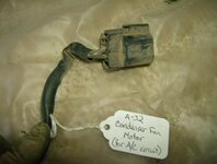
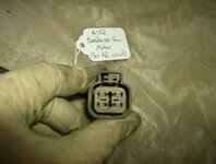
A-32: Condenser Fan Motor for AC Circuit

Connector available at: NMWP 4P Female.
 

Attachments

  • A-32CondenserFanMotorforACCircuitB.jpg
    A-32CondenserFanMotorforACCircuitB.jpg
    39.4 KB · Views: 499
  • A-32CondenserFanMotorforACCircuitA.jpg
    A-32CondenserFanMotorforACCircuitA.jpg
    33.2 KB · Views: 414
  • A-32.jpg
    A-32.jpg
    14.4 KB · Views: 1,100
Last edited:
A-33: Front Turn Signal Light Left Side
 

Attachments

  • A-33FrontTurnSignalLightLeftSideB.jpg
    A-33FrontTurnSignalLightLeftSideB.jpg
    42.2 KB · Views: 309
  • A-33FrontTurnSignalLightLeftSideA.jpg
    A-33FrontTurnSignalLightLeftSideA.jpg
    42.2 KB · Views: 328
  • A-33.jpg
    A-33.jpg
    12.2 KB · Views: 1,136

Attachments

  • A-40.jpg
    A-40.jpg
    15 KB · Views: 1,266
  • A-40RadiatorFanAssemblyA.jpg
    A-40RadiatorFanAssemblyA.jpg
    36.9 KB · Views: 414
  • A-40RadiatorFanAssemblyB.jpg
    A-40RadiatorFanAssemblyB.jpg
    37.8 KB · Views: 412
Last edited:
A-41: Front Turn Signal Light Right Side
 

Attachments

  • A-41FrontTurnSignalLightRightSideB.jpg
    A-41FrontTurnSignalLightRightSideB.jpg
    38.9 KB · Views: 366
  • A-41.jpg
    A-41.jpg
    12.1 KB · Views: 1,033
  • A-41FrontTurnSignalLightRightSideA.jpg
    A-41FrontTurnSignalLightRightSideA.jpg
    40.3 KB · Views: 400
A-42: Radiator Water Level Switch

Connector available at: DSD02 F.
 

Attachments

  • A-42RadiatorWaterLevelSwitchA.jpg
    A-42RadiatorWaterLevelSwitchA.jpg
    35.7 KB · Views: 383
  • A-42.jpg
    A-42.jpg
    10 KB · Views: 1,186
  • A-42RadiatorWaterLevelSwitchB.jpg
    A-42RadiatorWaterLevelSwitchB.jpg
    40.4 KB · Views: 394
Last edited:
Attachments

  • A-43FogLightRightSideB.jpg
    A-43FogLightRightSideB.jpg
    43.3 KB · Views: 306
  • A-43FogLightRightSideA.jpg
    A-43FogLightRightSideA.jpg
    40.1 KB · Views: 268
  • A-43.jpg
    A-43.jpg
    12 KB · Views: 1,036
Last edited:
A-44 and A-45: Horn Right Side
 

Attachments

  • A-44.jpg
    A-44.jpg
    2.3 KB · Views: 1,089
  • A-45.jpg
    A-45.jpg
    2.3 KB · Views: 1,109
  • A-44andA-45HornRightSide.jpg
    A-44andA-45HornRightSide.jpg
    37 KB · Views: 239
A-46: Headlight Right Side
 

Attachments

  • A-46HeadlightRightSideA.jpg
    A-46HeadlightRightSideA.jpg
    40.3 KB · Views: 337
  • A-46.jpg
    A-46.jpg
    8.1 KB · Views: 1,015
  • A-46HeadlightRightSideB.jpg
    A-46HeadlightRightSideB.jpg
    41.7 KB · Views: 289
A-47: Front Combination Light Right Side
 

Attachments

  • A-47FrontCombinationLightRightSideA.jpg
    A-47FrontCombinationLightRightSideA.jpg
    45.7 KB · Views: 317
  • A-47FrontCombinationLightRightSideB.jpg
    A-47FrontCombinationLightRightSideB.jpg
    46.9 KB · Views: 279
  • A-47.jpg
    A-47.jpg
    12.2 KB · Views: 1,046
A-48: Front Combination Light Right Side
 

Attachments

  • A-48FrontCombinationLightRightSideA.jpg
    A-48FrontCombinationLightRightSideA.jpg
    40.7 KB · Views: 279
  • A-48.jpg
    A-48.jpg
    12.3 KB · Views: 1,094
  • A-48FrontCombinationLightRightSideB.jpg
    A-48FrontCombinationLightRightSideB.jpg
    39.7 KB · Views: 273
A-49: Pop-Up Motor Right Side

The pop-up motor harness connector is available at: NMWP 6P Female.

The mating connector for the pop-up motor is available at: NMWP 6P Male.
 

Attachments

  • A-49Pop-UpMotorRightSideB.jpg
    A-49Pop-UpMotorRightSideB.jpg
    40.6 KB · Views: 327
  • A-49Pop-UpMotorRightSideA.jpg
    A-49Pop-UpMotorRightSideA.jpg
    43.5 KB · Views: 311
  • A-49.jpg
    A-49.jpg
    17 KB · Views: 825
Last edited:
Attachments

  • A-50.jpg
    A-50.jpg
    11.8 KB · Views: 750
  • A-50HoodSwitchA.jpg
    A-50HoodSwitchA.jpg
    35.9 KB · Views: 377
  • A-50HoodSwitchB.jpg
    A-50HoodSwitchB.jpg
    35.6 KB · Views: 330
Last edited:
A-52: Engine Control Wiring Harness and Engine Compartment Wiring Harness Combination (larger, four wires)

This is one of the connections that join this harness and the engine control harness together. Specifically, it joins with this connection on the Engine Control Harness: The 1990 Engine Control Wiring Harness.

NOTE: This is one of the connections UNDERNEATH the fuse box; there are no connections running to the fuse box itself.
 

Attachments

  • A-52.jpg
    A-52.jpg
    13.8 KB · Views: 777
  • A-52EngineControlWiringHarnessandEngineCompartmentWiringHarnessCombinationA2.jpg
    A-52EngineControlWiringHarnessandEngineCompartmentWiringHarnessCombinationA2.jpg
    41.4 KB · Views: 401
  • A-52EngineControlWiringHarnessandEngineCompartmentWiringHarnessCombinationB.jpg
    A-52EngineControlWiringHarnessandEngineCompartmentWiringHarnessCombinationB.jpg
    42.7 KB · Views: 434
Last edited:
A-53: Engine Control Wiring Harness and Engine Compartment Wiring Harness Combination (small, single wire)
This is one of the connections that join this harness and the engine control harness together. Specifically, it joins with this connection on the Engine Control Wiring Harness: The 1990 Engine Control Wiring Harness.

NOTE: This is one of the connections UNDERNEATH the fuse box; there are no connections running to the fuse box itself.
 

Attachments

  • A-53.jpg
    A-53.jpg
    8.8 KB · Views: 745
  • A-53EngineControlWiringHarnessandEngineCompartmentWiringHarnessCombinationA.jpg
    A-53EngineControlWiringHarnessandEngineCompartmentWiringHarnessCombinationA.jpg
    38.6 KB · Views: 378
  • A-53EngineControlWiringHarnessandEngineCompartmentWiringHarnessCombinationB.jpg
    A-53EngineControlWiringHarnessandEngineCompartmentWiringHarnessCombinationB.jpg
    41.3 KB · Views: 369
Last edited:
B-17: Power Steering Pressure Switch
 

Attachments

  • B-17PowerSteeringPressureSwitchA.jpg
    B-17PowerSteeringPressureSwitchA.jpg
    47 KB · Views: 365
  • B-17PowerSteeringPressureSwitchB.jpg
    B-17PowerSteeringPressureSwitchB.jpg
    48.5 KB · Views: 383
  • B-17.jpg
    B-17.jpg
    8.5 KB · Views: 868
Support Vendors who Support the DSM Community
Boosted Fabrication ECM Tuning ExtremePSI Fuel Injector Clinic Innovation Products Jacks Transmissions JNZ Tuning Kiggly Racing Morrison Fabrications MyMitsubishiStore.com RixRacing RockAuto RTM Racing STM Tuned

Latest posts

Build Thread Updates

Vendor Updates

Latest Classifieds

Back
Top