The Top DSM Community on the Web

For 1990-1999 Mitsubishi Eclipse, Eagle Talon, Plymouth Laser, and Galant VR-4 Owners. Log in to remove most ads.

Please Support RTM Racing
Please Support Morrison Fabrication

1G What kinds of metal connectors do 1G DSMs use inside plastic connectors?

This site may earn a commission from merchant
affiliate links, including eBay, Amazon, and others.

This site may earn a commission from merchant affiliate links, including eBay, Amazon, and others.

XC92

Proven Member
1,573
362
Jul 22, 2020
Queens, New_York
I'm not sure if I'm using the correct terminology. What I mean is what kinds of individual metal connectors, male and female, terminate the various wires that go into the actual plastic connectors, male and female, that connect various sensors and actuators to the wiring harness?

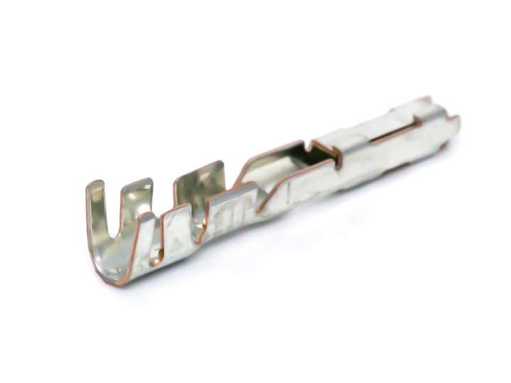
Yesterday while replacing the reverse switch on the manual trans on my 1G Talon Tsi, I accidentally severed one of the 2 wires that go into the Engine Coolant Temperature Switch connector next to the coolant cap. So I cut the other wire and took it inside to have a look, and was able to remove both connectors, which appear to be what I believe are called spade crimp connectors, in this case I think 2.8mm.

I'm referring to these, not to the plastic connectors they're inserted into, of which there are many types in a typical car. That's a whole other matter. I'm wondering what these are properly called, and what kinds and sizes a 1G 2.0 turbo DSM typically uses. I'd like to buy a whole set of them to have on hand for such situations.

I'm going to be removing a bunch of parts in the engine bay soon to clean things up, replace some gaskets and o-rings and fix some idle issues, and there's a good chance that I'll be repairing some broken or frayed connector wiring. Is it mostly 2.8mm, or also 4.8mm & 6.3mm?

Are yet other kinds of connectors used, like MOLEX, DuPont, etc.? Like the ones that go inside the diagnostic port under the dash or that connect various wiring harnesses?

I was able to use what I believe are called butt connectors + heat shrink to reconnect the wires to the existing female spade connectors, but in the future I might not be so lucky so it's a good idea to have some on hand. Plus it's the right way to fix things.

I have several crimping tools, both the free-swinging and ratcheting kind, so I'm probably good there. I've also got plenty of heat shrink tubing.

And yeah, I know, this is very basic stuff. But I don't know what these things are properly called so I can't search for them. Took a while to find the little I did. Is there a comprehensive reference somewhere?
 
Last edited:
Here, @brads can hook you up and is a very reliable source!!! I have ordered quite a few connectors from him in the past and always pleased. I think his products are also available through one of our vendors.
 
I believe most of the connectors Mitsubishi used are Sumitomo. The catalogs are a pain trying to look through but have the plastic housing and the internal male & female internals.
 

Attachments

  • Sumitomo-us-series-connectors-catalog.pdf
    5.1 MB · Views: 27
Hey thanks. Very helpful. And now I know what the different parts are called so I can ask questions intelligently. E.g. the metal part that crimps over the exposed wire end is a terminal, coming in male & female versions, that is then inserted into each respective plastic connector, which it should click and lock into.

Turns out that I was asking about terminals, just didn't know what they were called. My connectors appear to be ok so no immediate need to replace any. There seem to be a lot of different kinds of terminals, similar to each other with minor variations.

I need to do some more research to see which ones I need. Probably best to have various terminals on hand in male & female for future repairs as I'm probably going to have a number break on me after 30 years.
 
Thanks. I'm starting to get the hang of this.

Basically, harness--wire--seal--crimped terminal--connector.
 
The slight variations of different terminals between the different series of connectors, make them incompatible. You may find that some terminals are shared between different series, but this isn't that common.

I do source the terminals and wire seals too, and have been doing it for 20 years for these cars. Sumitomo is one brand used. Another common one was called Mitsubishi back then, but the connector line has since been sold and a few other companies are the OEM for them now. I try to make a point of only sourcing OE components. The aftermarket connector makers will sometimes make parts that have problems either on installation, or over the long term.

You need the wire seals matched to the size of wire you are using, if you are trying to keep the connector sealed to protect it from moisture. Extreme PSI sells the kits. I recommend replacing connectors too, if you are going through the trouble of replacing wire. Especially the ones near heat sources. 30 years old baked connectors and baked wire is pretty brittle.
 
Drives me crazy how there can be parts that serve such similar functions and look so similar, and yet are just different enough to not work in place of each other. Moulding clips and wiring seem most common. Stuff that is never really seen, and should be standardized in a sane world. Fasteners too, though at least for those I can sometimes see why minor changes are specific to application (thread pitch, head flange, shouldered…etc.). 30 years later it’s buy-it/try-it, and if you’re working on something unfamiliar, left wondering if they “always” were a little janky, or do you need something different. :cry:
 
One thing I appreciate about buying these parts from Brads (Sheridan Engineering) is that he will ask me what wire size I plan on using, if I forget to mention it in my order. Because if there are seals involved then the seal ID needs to fit the OD of the wire insulation pretty close. And this last time (for an engine coolant temperature sensor plug) the wire size affected which terminals he sent - there were no seals for that one. If you are using SXL, GXL, or TXL (that's the insulation thickness when you are talking about engine compartment wire) he can get the wire OD from that plus the wire gauge you are using.
 
I actually had to repair that exact connector a few weeks ago and had to improvise because I didn't have the right terminals and seals. It appears to have help up so far but at some point I'll have to do it right, so I'll look to these sources for supplies.

Meanwhile, do you have any idea why a 30 year old stock radio-cassette unit would cut in and out on each of the speakers? I traced it down to either the connectors or unit as the wiring and speakers appear to be fine (I did a continuity test on each speaker's + & - terminals and all checked out fine).

When I jiggle the connectors on the back, the speakers all play, but only if I jiggle it a certain way. I also cleaned up each male and female terminal and made sure there was positive contact between each.

I'm now thinking that it's the circuit board where the male terminals are soldered to the board. Do those tend to go bad over time, or something else on the board that they're soldered to? It's driving me crazy. I'll probably get a new radio eventually, but for now I'm stuck with this and want it to work.

...Ok, never mind, figured it out. The male spade connectors on the radio had desoldered on the other side of the circuit board. I could see them wiggle. That's why jiggling momentarily fixed things. The original solders weren't that good, not enough solder and it was bound to come undone eventually with car vibrations. So I resoldered each one then reconnected the radio, and voila, it worked, like new, every speaker being driven and the front-back left-right balance working properly. The primary purpose of solder is to make a mechanical, not an electrical connection, although that too. One problem down, dozens left to go...
 
Last edited:
The male spade connectors on the radio had desoldered on the other side of the circuit board. I could see them wiggle.

I had a couple of OEM radios that had that problem where the original solder fractured at the connectors. I used silver solder when I reflowed the joints, it's stronger than the typical 60/40 solder.
 
I had a couple of OEM radios that had that problem where the original solder fractured at the connectors. I used silver solder when I reflowed the joints, it's stronger than the typical 60/40 solder.
I used whatever solder I had, lead based. If it doesn't hold up then I'll use the silver kind. But obviously you're going to need a stronger or different type of solder where vibration, heat, cold, etc., are going to be issues.

Next up, removing the car's ancient security system and installing a very basic one that lets me remotely lock and unlock the doors again. I wonder if there are ones that use chip detectors like with newer credit cards that you just tap?
 
Silver solder for electronics use only has a small amount of silver in the mix but it makes big difference in it's strength. Sn62Pb36Ag2 vs Sn63Pb37 or Sn60Pb40.
Thanks for the tip, I didn't know this. But what's done is done but if the new solder doesn't hold up then I'll definitely remove it and use silver solder next time, and good to know for any future soldering I'll need to do on the car.

Come to think of it, I do. The rear window defroster tab broke off years ago and I've never been able to figure out how to fix it. I tried to resolder it with a butane-powered soldering iron but that didn't work and I was afraid of cracking the glass with the heat. Any suggestions? I mean the part that connects the wire to the heating element embedded in or glued onto the glass.
 
Support Vendors who Support the DSM Community
Boosted Fabrication ECM Tuning ExtremePSI Fuel Injector Clinic Innovation Products Jacks Transmissions JNZ Tuning Kiggly Racing Morrison Fabrications MyMitsubishiStore.com RixRacing RockAuto RTM Racing STM Tuned

Latest posts

Build Thread Updates

Vendor Updates

Latest Classifieds

Back
Top