architechnik
15+ Year Contributor
- 690
- 10
- Jun 21, 2007
-
Glad,
Oregon
What could be factory tapped on the TPS sensor wire near the ECU?
I've been rewiring much of my engine bay all the way back to the ECU (refreshing 25+ year old wires, multiple relays/MPI replacement, dedicating power sources & grounds, individual wire looms, etc).
I've found an issue with the TPS signal wire (Green/White Pin 19) being tapped to some other line. I've checked all the materials I have and searched online and have found nothing that indicates it should be routed to something else. It's definitely a factory tap w/ the metal crimp and factory electrical tape.
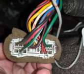
Here's picture of where I clipped the wires (verified the TPS signal). You can see it's also the one that runs to that connector in the background by the shifter cables; that's the cluster that runs toward the ignition.
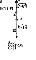
Here's the diagram segment that shows a clear straight line to the ECU:
Here's that connector from the other side, which appears to be C-67 in the diagrams, although I have not found a single source of C-67 pinout directions. Basically C-67 is just a connector; it refers to it in may locations from ABS to diagnostics, to CEL...
Vehicle Details: '94 M/T GSX purchased entirely stock (except maybe a head unit and radar detector?) w/ lots of factory add-ons.
I was thinking it was maybe an anti-theft register or perhaps a tap to turn off injectors at WOT on start (anti-flooding measure also used for compression testing). But neither of these are documented in the wiring diagrams for sensor/ECU wiring or anti-theft units. Any direction is appreciated.
I've been rewiring much of my engine bay all the way back to the ECU (refreshing 25+ year old wires, multiple relays/MPI replacement, dedicating power sources & grounds, individual wire looms, etc).
I've found an issue with the TPS signal wire (Green/White Pin 19) being tapped to some other line. I've checked all the materials I have and searched online and have found nothing that indicates it should be routed to something else. It's definitely a factory tap w/ the metal crimp and factory electrical tape.
Here's picture of where I clipped the wires (verified the TPS signal). You can see it's also the one that runs to that connector in the background by the shifter cables; that's the cluster that runs toward the ignition.
You must be logged in to view this image or video.
You must be logged in to view this image or video.
Here's the diagram segment that shows a clear straight line to the ECU:
You must be logged in to view this image or video.
Here's that connector from the other side, which appears to be C-67 in the diagrams, although I have not found a single source of C-67 pinout directions. Basically C-67 is just a connector; it refers to it in may locations from ABS to diagnostics, to CEL...
You must be logged in to view this image or video.
You must be logged in to view this image or video.
Vehicle Details: '94 M/T GSX purchased entirely stock (except maybe a head unit and radar detector?) w/ lots of factory add-ons.
I was thinking it was maybe an anti-theft register or perhaps a tap to turn off injectors at WOT on start (anti-flooding measure also used for compression testing). But neither of these are documented in the wiring diagrams for sensor/ECU wiring or anti-theft units. Any direction is appreciated.