This article will cover the planning and fabricating of a sheet metal duct for a side mount intercooler (smic), but the techniques can be used in any simple ducting you may want to make for your car.
A front mount intercooler (fmic) is one of the first things many owners swap into a DSM to improve the performance of the car, as the stock side mount intercooler (smic) is fairly small and will heat soak after only a couple of hard back-to-back pulls. However, with proper ducting, and by sealing the duct to the core, you can improve the performance of the stock smic and spend your hard earned money on other fun bits until you absolutely have to go larger. A new duct will also be in order if you upgrade the smic. In this example, I have made a duct for my Dejon Big SMIC, as the stock piece is nowhere close to fitting the larger core on this IC.
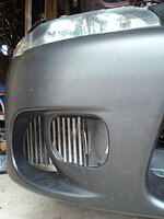
As an aside to this install, I recently did a 2gb Eclipse front bumper cover swap on my '96 Talon, which gives me the added benefit of increased area on the fascia where air can enter the duct, as opposed to the relatively tiny opening for the stock 2ga bumper. I had previously made a custom duct for my 2ga bumper, removing the passenger side foglight/bracket and running the duct over to fill that area, and it was a definite improvement over the stock setup. So don't think that the cover swap is necessary, I just think it's a better starting point for more airflow to a SMIC on a 2ga DSM.
So, first things first: Read up on how to remove the front bumper/cover from your car, as you'll want to do that. It's not impossible to do the duct with the bumper/cover on the car, but for all the time and frustration it adds, you are better off just pulling it. It really makes this a lot easier overall. You can leave your cover attached to the bumper core if you are starting fresh, so that replacing it temporarily during the duct fitting process is easier. If your cover is not attached to the actual bumper core due to past work, then you are 4 bolts ahead of everyone else, and you can just remove the cover. If you google '2g front bumper removal' you'll find a great visual step-by-step writeup for this, and while I've never pulled a bumper off a 1g, I'd imagine it's not too different from a 2g. There are articles here on Tuners for bumper removal too, but none I could find with photos.
Here's a materials list:
Hand tools required to R&R the bumper/cover and install the finished duct
About 9 sq feet of heavy cardboard (a 3'x3' piece was plenty for this project)
Roll of masking or duct tape for the mockup
Roll of 'real' flue/duct tape to seal the final duct (it's stronger than regular duct tape)
Box cutter
Leather gloves
Sharpie pen
Tin snips (mine are offset snips...makes cutting deeper into the sheet metal easier)
Rubber mallet or similar
Workbench or sturdy straight edged table/countertop for light hammering
Drill and appropriate size bit for the rivets you'll use
Aluminum or other sheet metal (I used 0.032" aluminum because it cuts relatively easily and is rustproof)
Rivet gun
Aluminum rivets of appropriate length/width. (Double your metal thickness and add a little for good measure. I used 1/8" diameter x 1/8" grip range.)
Random nuts/bolts for hanging the duct
Be Careful! Use some common sense when using the box cutter, drill, and tin snips! Don't draw the knife towards you, cut away from your body. Sheet metal can be quite sharp when cut with the snips, so be aware of all the edges, and the little scraps and bits that are littering the ground around you. Wear the gloves! When you are drilling the holes for the rivets, support the hole from inside the duct with a piece of wood...don't put your fingers under there!
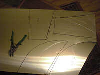
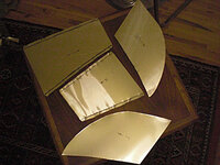
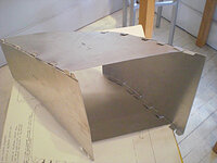
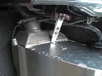
Here's the car up on jackstands, front bumper/cover off, Dejon Big SMIC mounted under the front fender. Use the cardboard to make a template for the duct, one panel at a time, starting a little larger than actual size and trimming back each panel to fit. I started with the upper and lower panels, as they are essentially identical here, cutting them to fit the inside curve of the bumper cover. I then added the sides. I had to trim the upper and lower panels a bit once the sides were attached, so I could curve around the frame a little better, so don't expect to have it all go together the first time. You'll be taping, cutting, re-taping...there is much trimming and tweaking in this step, and the more you do here the better. It's much harder to trim and refit in metal than in cardboard. While fitting, make sure that all curved surfaces are indeed curved, and flat ones are flat, as minor differences there can be frustrating later. Scoring the cardboard on the outside of the curve helps to get it to cooperate if it's stiff.
A front mount intercooler (fmic) is one of the first things many owners swap into a DSM to improve the performance of the car, as the stock side mount intercooler (smic) is fairly small and will heat soak after only a couple of hard back-to-back pulls. However, with proper ducting, and by sealing the duct to the core, you can improve the performance of the stock smic and spend your hard earned money on other fun bits until you absolutely have to go larger. A new duct will also be in order if you upgrade the smic. In this example, I have made a duct for my Dejon Big SMIC, as the stock piece is nowhere close to fitting the larger core on this IC.
As an aside to this install, I recently did a 2gb Eclipse front bumper cover swap on my '96 Talon, which gives me the added benefit of increased area on the fascia where air can enter the duct, as opposed to the relatively tiny opening for the stock 2ga bumper. I had previously made a custom duct for my 2ga bumper, removing the passenger side foglight/bracket and running the duct over to fill that area, and it was a definite improvement over the stock setup. So don't think that the cover swap is necessary, I just think it's a better starting point for more airflow to a SMIC on a 2ga DSM.
So, first things first: Read up on how to remove the front bumper/cover from your car, as you'll want to do that. It's not impossible to do the duct with the bumper/cover on the car, but for all the time and frustration it adds, you are better off just pulling it. It really makes this a lot easier overall. You can leave your cover attached to the bumper core if you are starting fresh, so that replacing it temporarily during the duct fitting process is easier. If your cover is not attached to the actual bumper core due to past work, then you are 4 bolts ahead of everyone else, and you can just remove the cover. If you google '2g front bumper removal' you'll find a great visual step-by-step writeup for this, and while I've never pulled a bumper off a 1g, I'd imagine it's not too different from a 2g. There are articles here on Tuners for bumper removal too, but none I could find with photos.
Here's a materials list:
Hand tools required to R&R the bumper/cover and install the finished duct
About 9 sq feet of heavy cardboard (a 3'x3' piece was plenty for this project)
Roll of masking or duct tape for the mockup
Roll of 'real' flue/duct tape to seal the final duct (it's stronger than regular duct tape)
Box cutter
Leather gloves
Sharpie pen
Tin snips (mine are offset snips...makes cutting deeper into the sheet metal easier)
Rubber mallet or similar
Workbench or sturdy straight edged table/countertop for light hammering
Drill and appropriate size bit for the rivets you'll use
Aluminum or other sheet metal (I used 0.032" aluminum because it cuts relatively easily and is rustproof)
Rivet gun
Aluminum rivets of appropriate length/width. (Double your metal thickness and add a little for good measure. I used 1/8" diameter x 1/8" grip range.)
Random nuts/bolts for hanging the duct
Be Careful! Use some common sense when using the box cutter, drill, and tin snips! Don't draw the knife towards you, cut away from your body. Sheet metal can be quite sharp when cut with the snips, so be aware of all the edges, and the little scraps and bits that are littering the ground around you. Wear the gloves! When you are drilling the holes for the rivets, support the hole from inside the duct with a piece of wood...don't put your fingers under there!
Here's the car up on jackstands, front bumper/cover off, Dejon Big SMIC mounted under the front fender. Use the cardboard to make a template for the duct, one panel at a time, starting a little larger than actual size and trimming back each panel to fit. I started with the upper and lower panels, as they are essentially identical here, cutting them to fit the inside curve of the bumper cover. I then added the sides. I had to trim the upper and lower panels a bit once the sides were attached, so I could curve around the frame a little better, so don't expect to have it all go together the first time. You'll be taping, cutting, re-taping...there is much trimming and tweaking in this step, and the more you do here the better. It's much harder to trim and refit in metal than in cardboard. While fitting, make sure that all curved surfaces are indeed curved, and flat ones are flat, as minor differences there can be frustrating later. Scoring the cardboard on the outside of the curve helps to get it to cooperate if it's stiff.
Attachments
Last edited by a moderator: