The Top DSM Community on the Web

For 1990-1999 Mitsubishi Eclipse, Eagle Talon, Plymouth Laser, and Galant VR-4 Owners. Log in to remove most ads.

Please Support STM Tuned

2G No power to the ECU

This site may earn a commission from merchant
affiliate links, including eBay, Amazon, and others.

This site may earn a commission from merchant affiliate links, including eBay, Amazon, and others.

they all have power. so why isn't it working.

Check continuity between ecu oins 8,38,12,&24 and there respective mpi/fuel relay plug pin locations.

if that checks out, try the other ecu.

Options are relay,ecu,or wiring between the two if you do in fact have power everywhere thats required.;

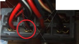
Check for a broken wire in the harness if you haven't checked it yet. Sniver Knows I had a similar problem and to find there was a broken wire.

I linked him to that post once, described it, and similar situations. he ended up replacing the original harness with another used untested condition harness, and believes there to be no flaws to it that he is aware of.

Well despite he has a 95 harness and had to custom wire the relays.:sneaky:

Will you just fix this poor dsm already, I'm long grown tired of checking in with the wife(you/your car) everyday to hear her new issues.:boring: ..... ROFLROFL

I'm just kidding, your almost there, I mean it ran, that has to be awesome after all this , right?!:ninja:
 
what controls the 2 ecu power wires? i think this is my issue. the are red with black stripes.................. those aren't the same 2 that go to the relay are they?

this confuses me :confused:

are you talking about the wires that control pins 12 & 25 on the ECU?

or are you talking about the red w/black stripe wires at the MPI relay?

Battery (+) --> 20A ENGINE Fuse --> red/black wire(s) --> MPI Relay --> Red wire to pins 12 & 25 (NO BLACK STRIPE)

you're describing one thing and referencing the wires from another. please take a picture so we can SEE which wires you're talking about.

also, can you test battery voltage for me? just want to know how many volts it's giving you with the charger disconnected please. :) if you have access to a battery tester, that would be even better. (Wouldn't it be nice if it was something that simple LOL)
 
the battery has 12v

I did not engineer the relay because the 1 plug relay came in today,

I plugged it up and it ran, it didn't even make a complete crank and fired right up.

2 hrs later i re-attatched my intercooler piping and hooked up my maf.

went to start the car and nothing.

I tried my oe ecu with no results.

I'm considering that somehow the mpi relay crapped out.

As the harness has not been tampered with. I know factory from technicians trained to fix and try to re-implicate factory like quality, their isn't any exposed wires or blown fuses.

i even removed the turbo timer intermediate harness just for giggles with no change, as all ignition wires still recieved 12v.

because......

from---- ignition 12v ----to------> fuse has 12v ------from---------to--> mpi relay 12v ---from----------> has only 7v on two spots --------to--------> ecu --------- pin 12&25 have 0.75v-------- no start

bad relay?
 
You must be logged in to view this image or video.


Look at this image as if your looking at the back of the plug.

Wires:
1) Black/Blue
2) Red
3) Black/Red
4) Red/Black
5) White/Red
6) Blue/Green
7) Blue/White
8) Red/Black

MPI Relay
1) This step checks ignition supply voltage to PCM. Disconnect PCM harness connector. Turn ignition on. Using DVOM, measure voltage between PCM harness connector terming #82 and vehicle ground. If battery voltage is present, go to step 2). If battery voltage is not present, check and repair circuit between ignition switch and PCM harness connector.
2) This step checks battery supply voltage of MPI relay. Using DVOM, measure voltage between ternimal #4 and #8 of relay harness connector and vehicle ground. If voltage is battery voltage, go to step 3). If voltage is not battery voltage, check and repair circuit between battery and MPI relay.
3) This step checks continuity of circuit between MPI relay and PCM. Disconnect PCM harness connector. Using DVOM, check continuity between MPI relay harness connector terminal #6 and PCM harness connector terminal #38. If continuity exists, go to step 4). If continuity does not exist, check and repair circuits between MPI relay harness connector and PCM.
4) this step checks continuity of circuit between MPI realy and PCM. Check continuity between MPI relay harness connector terminal #2 and PCM harness connector terminals #12 and #25. If continuity exists go to step 5). If continuity does not exist, check and repair circuits between MPI relay harness connector and PCM.
5) This step check supply voltage to MPI relay actuator. Connect PCM and MPI relay harness connectors. Using DVOM, backprobe MPI relay terminal #3. With engine cranking, voltage should be 8 volts or greater. Start and run engine at 2500 RPM or greater. Of battery voltage is present, harness is okay. If voltage is not battery voltage, go to step 6)
6) If MPI relay test okay in following steps, substitute PCM with known good unit and retest. Measure resistance between relay terminals #5 and #7. Resistance should be approximately 90 ohms. Check continuity between terminals #6 and #8. Continuity should exist in only one direction. Replace MPI relay if continuity is not as specified.
7) Connect 12-volt pwer source between relay terminals #5 and #7. Connect positive lead to terminal #7. With relay energized, batter voltage should exist between terminals #1 and #5. With pwer source removed, voltage should not exist.
8) Move 12-volt pwer source to relay terminals #6 and #8. Connect positive lead to terminal #7. With relay energized, continuity should exist between terminals #2 and #4 and between terminals #3 and #4. With pwer source removed, continuity should not exist. Replace MPI relay if measurements are not as specified.

If you think your MPI relay is bad I would start with step 6). Thats what I started with and did not have to go through the first 5 steps.

You must be logged in to view this image or video.


All taken from How to Check MPI Relay (DIY DSMers)
 
good link man I'm gona test it today sometime.

step 1. 12volts

2. 12 volts

3.continuityt is .5 ohms

4. #12 has continuity of 57 ohms, and #25 has 48 ohms

5.12volts and 11.7 wghen cranking


6. resistance is 45.9,ohms #6 & #8 has -0.9 ohms

7.12 volts and 0.75 volts when no power is applied

8. continuity is -0.9 ohms and then on the next it has -0.9 ohms

this means the new relay crapped out correct.
 
Last edited:
Continuity: the absence of interruption, basically meaning that there is NO interruption of power through a circuit or wire.

you're readings should be in Ohms.

if you HAVE continuity, your DVOM should read 0.0 Ohms

IF you DO NOT have continuity, your readings will be greater than 0.1 Ohms

I have a suspicion that you are not running some of these tests correctly.

I'll run these same tests when I get home tonight, and take pictures so you can see how they're supposed to be performed.
 
my readings are in ohms
 
MPI looks good at a glance, though I'm on a phone and fliping back and forth to compare answers to the results.

For step 4, your result indicates a isssue.

50 some ohms between the mpi terminal and the ecu terminal tells me a wiring issue, likely corrosion in a couple wires.

You not posting units throws us both off apparenly. It conveyes a unsureness to me, and makes me question your results. Just saying.


Sent from my Droid
 
steps 3 and 4 should return 0.0 Ohms. If they return anything else, it's wiring, not the relay.

I'm going to be blunt, I think you did that test wrong.

as soon as you got .5 with step 3, you should have stopped there, and double checked your readings. did you make sure that's #6 when looking at the BACK of the plug? not the front.

can you please humor me, and test for continuity between pin 6 (circled in red) and pins 12 and 25 on the ECU and post the results.
 

Attachments

  • 0630002317-2.jpg
    0630002317-2.jpg
    44.8 KB · Views: 292
Continuity: the absence of interruption, basically meaning that there is NO interruption of power through a circuit or wire.

you're readings should be in Ohms.

if you HAVE continuity, your DVOM should read 0.0 Ohms

IF you DO NOT have continuity, your readings will be greater than 0.1 Ohms

I have a suspicion that you are not running some of these tests correctly.

I'll run these same tests when I get home tonight, and take pictures so you can see how they're supposed to be performed.

Almost.... continuity is a reading of any ohms. You have continuity, try it. Your body might have 234 megaohms, or a sh!t ton of resistance in common terms.

No continuity is "out of limit, OFL, ect" like with a unnconnected wire, or two leads freely in the air.

You should always get your base resistance, touch your leads together and see what you "zero" is. My multi meter is .1 ohms, its cheap.

Any wire that's has a resistance of over 1ohm is cause for oem to warrant investigation. That's 1.1ohm per my multi meter. Get that idea, right?

Sent from my Droid
 
Last edited:
steps 3 and 4 should return 0.0 Ohms. If they return anything else, it's wiring, not the relay.

I'm going to be blunt, I think you did that test wrong.

as soon as you got .5 with step 3, you should have stopped there, and double checked your readings. did you make sure that's #6 when looking at the BACK of the plug? not the front.

can you please humor me, and test for continuity between pin 6 (circled in red) and pins 12 and 25 on the ECU and post the results.

Up to 1 ohm is permitable,..step 3 is good.


Sent from my Droid
 
updated the post with the ohms
 
steps 3 and 4 should return 0.0 Ohms. If they return anything else, it's wiring, not the relay.

I'm going to be blunt, I think you did that test wrong.

as soon as you got .5 with step 3, you should have stopped there, and double checked your readings. did you make sure that's #6 when looking at the BACK of the plug? not the front.

can you please humor me, and test for continuity between pin 6 (circled in red) and pins 12 and 25 on the ECU and post the results.

with both unplugged checking what you asked it's ,2 ohms on both
 
with both unplugged checking what you asked it's ,2 ohms on both

2 ohms wouldn't make it stop working, its a tad big, but your multimeter may have a 1ohm "zero"

Maybe I mis read your findings, why do you feel the relay is bad, based on what step. explain, and be thorough.
 
0.2 ohms not 2 i apologize, i didn't realize i put a comma instead of a . on the 2 in the previous post
I think it's the relay because nothing changed from the time it started up and ran and then when it wouldn't restart.
the relay is not switching the power over to the black blue wire for the fuel pump. for no apparent reason except in my eyes, the relay had to have crapped out for some random stupid reason.

and a few of the steps tit told me to check were incorrect from what they should be when checking the relay.
like the #6 check list, it is far from acurate like it should be.
otherwise I don't know.
 
Last edited:
Ok, sorry for my absence. My link v3 arrived on the 9th, and I've been focusing on my car.

I'm sure something has changed since your last post. Care to give us a fresh rundown of what's going on?

Sent from my T-Mobile G1 using Tapatalk
 
that last post is it... you told me to do what you said and nothing more untill I'm given direction... And I'm waiting for the next thing to do.

Can't ever accuse me of not being patient. :D


although i had found this thread, even though the fellow was testing for the wrong mfi relay it still explained to me why my lights on the dash were staying on, in hindsite that could be usefull to others.

...
MFI relay keeps dash lights on when bad sometimes. even though this is no longer an issue i am having.

\


MPI relay schematics? | Galant VR-4 > Technical Discussions | GalantVR-4.org Mitsubishi Galant VR4 Forum
 
Last edited by a moderator:
Just pull the relay and jump the two sets of pins to bypass the relay and manually have it wired on for testing purposes. Use mechanics wire, or thinner gauge copper wire from house wire would work.

Does step 4 have 50+ohms omn the two wires? ... never addressed my previous post.

I'm back at the point where we've covered it all. What's next? Nothing without repeating.


Sent from my Droid
 
okay new data.

went to start over. and i did

every fuse good.

turned the key CEL came on and the car fired right up and ran I checked the mpi when it was running and all was good. I cut it off and it would not reststart again.... and no cel.

Confused i got to thinking the relay does seem to be good as you have specified, because it worked and i checked it while it was running.
So i said lets try the 95 oe computer and see what happens.

I plug it in and walla cel light comes on but with this ecu the car will crank, but stutter like crazy and never start, even though it's trying.

CEL comes on everytime with this ecu.

not the dsmlink ecu, I have brought the dsmlink ecu home and opened it up and i see something leaking on the board, and the board to me and my wife smells like metal. no foul odor comming from it.

I will most likely be finding someone to send it to to fix just in case, but it raises the question of why would this ecu make my car run and not the ecu that is in mint condition?

the parts on the ecu i am concerned with are highlighted in red, especially the capaciter right in the center and each photo is circled in red.
You must be logged in to view this image or video.


You must be logged in to view this image or video.

You must be logged in to view this image or video.

You must be logged in to view this image or video.

You must be logged in to view this image or video.

You must be logged in to view this image or video.


you can clearly see some yellowishgreenish gooy looking stuff even though it's not an abundance.

What year is the non eprom from? The link ecu is a 95, the other id assume is not?


Sent from my Droid
 
Try changing the plug wires. 95 oe ecu needs firing order to be different. Should be 2314 from left to right.

O O O O
2 3 1 4

Car should fire right up, no stutter. Give that a try and lemme know if it starts....

Sent from my T-Mobile G1 using Tapatalk
 
^ Is this still valid keeping in mind the 95 wiring harness? I wasn't sure, figured if the ecu were different years i'd go from there. Also what about the cas swap. He was doing it to 97+ specs , is that of any difference now that the harness is different?
 
That's how mine is. My setup:
1g CAS rewire
95 eprom (with link, I DID NOT invert CAS)
95 harness

Sent from my T-Mobile G1 using Tapatalk
 
I'll check the firing order to your spec, i had already changed them for the 1g swap and made sure they were still correct,

I didn't even consider the new wire harness into the equation, but the good ecu is also a 95 non eprom.

so what do you recon that means?

Can you post up the dummy pic for me to 100% make sure this DSM for idiots (patent Pending) is doing it correctly.
 
Last edited by a moderator:
If the link ecu ran it, unless you have the firing order on link inverted, you ought to be right.
 
Support Vendors who Support the DSM Community
Boosted Fabrication ECM Tuning ExtremePSI Fuel Injector Clinic Innovation Products Jacks Transmissions JNZ Tuning Kiggly Racing Morrison Fabrications MyMitsubishiStore.com RixRacing RockAuto RTM Racing STM Tuned

Latest posts

Build Thread Updates

Vendor Updates

Latest Classifieds

Back
Top