The Top DSM Community on the Web

For 1990-1999 Mitsubishi Eclipse, Eagle Talon, Plymouth Laser, and Galant VR-4 Owners. Log in to remove most ads.

Please Support STM Tuned
Please Support ExtremePSI

2G No power to the ECU

This site may earn a commission from merchant
affiliate links, including eBay, Amazon, and others.

This site may earn a commission from merchant affiliate links, including eBay, Amazon, and others.

my apologies,

It doesn't have a turbo timer in it'sself, although i have the wire harness for the turbo timer hooked up on my car, it's a good easy spot for refference to check for voltage.
I'm gona check the CAS as well. but untill i get a crank, It won't do any good.
 
Thanks rush, I'm pretty much positive this is some thing stupid simple. Now if only we could get it figured out.


Sent from my Droid
 
tonight:

i may have forgot to mention something that may or may not have any importance, and i did this because i felt is was un-important as my mechanic and i discussed it and found nothing wrong with the setup.
My new wiring harness failed to have abs brakes incorperated. we have removed them from many cars where they failed to even work so it's no something we were concerned with at the moment.

I went to the shop and worked on her tonight, when i noticed my headlights don't work anymore.
I turn the flashers on and they don't either, brakes nope.
So i checked every fuse on the entire car, and replaced every relay from my old harness that did work. still nothing.
I go through my old harness find all the grounds one at a time and then check the car and make sure they are also grounded, all good!
baffeled i check voltage on the ecu it has minimal like .251
i then check to see if i have power at my alternator and i do 14v as i have a battery charger on the entire time i work on the car.

it's strange that nothing is working now. no
so i tore apart my old harness and removed all the abs stuff, even the pins that go to the fuse panel.
i add all the junk back to my new harness and panel and nothing changed. and I' also put the new ignition switch in, and still no voltage to the turbo timer wires when the key is turned on.

I have a whole new set of problems that make no since considering everything is grounded properly and has the correct power supply.
I am so lost and frustrated.
I feel i could make a harness faster than diagnosing this crazy stuff

Is their a how to wire harness for a drag car with this engine and keep the dsmlink tuning?
I can hardwire the fuel pump, the starter, the headlights, the ecu and the mfi relay, the radiator fans, add coolant, oil, boost guages, the thing that concernes me is the cam sensor and being able to program my dsmlink if i do all that.
 
Post up a pic of this turbo timer harness.

I promise you, if you aren't capable of fixing this, then you surely can't create a new harness that will work any better.

Maybe its time to find someone more qualified to figure this out.You have as many issues as you did in January...
 
actually it has more issues now, before the new harness was put in.

It is the greddy turbo timer harness, verry simple.

Obviously now my issue is that my ignition isn't recieving power. neither are my headlights etc.......this harness i have is in mint condition and looks to have never been tampered with.

I know what every plug looks like and the wires coming from them, i know what all is connected in fusable links, and how many ground straps each harness has,

I have figured out alot of crazzy things such as the radiator fan has to be plugged in for the started ground to complete it's circuit,,
I also realize that my new harness is now out of a 97 gst and mine is a 98 gsx, every plug fits correctly, it just doesn't have abs.

my car is gutted so taking it somewhere is kinda out of the question at this point,

one thing i didn't check is if i am getting power from the harness on the drivers side i had to plug back into the dash and ignition.
 
The turbo timer harnnes to does not complete the complete the circuit if the timer is not present is what i would think, but i don't own own. does it look like this?

You must be logged in to view this image or video.


Do all of the pin have continuity as it sits?
 
it looks similar, and no it doesn't have to be plugged in, thats not how it's wired, this has been on the car since i baught it and before i blew it up and never was the timer installed, with no issues at all. I am going to go around town and see if any other machanics would be willing to takle the issue i guess, that is if i can afford it. as long as they can get it to crank and get power everywhere i can deal with the 1g swap and calibrations on dsmlink. I just hope they can understand that and not think i've screwed the system up with the swap, because i know most mechanics around here are weird like that. if it's not oe they don't normally wanna touch it.
 
OK, first of all, ENOUGH OF THIS! KeelesKustome, LISTEN/READ more closely to what Sniver is asking of you. you're going on wild-a$$ goose chases! He's taking time out of his day to help you, and you're not listening to a single thing he is saying. You're just hunting around blindly, jumping from one thing to the next. you're lucky he's as patient as he is, because I know if it was me, I'd have given up on you a long time ago.

if he asks you to check pin # z4565290509 on the flux capacitor, check the F***ing pin, report your results and DO NOTHING ELSE until he gets back to you. you're obviously not able to figure this out on your own, that's why you asked for help. So wait for instructions from someone who KNOWS WHAT THEY'RE DOING! then do as they ask.

after just a few posts, Sniver managed to help me figure out that my ECU was bad (thanks Sniver), if you'd just do what he's asking, I'm sure he could help you too.

My advice:

make a list of everything that's wrong with your car right now, and post it in a single post. I'm sure Sniver will be able to find common problems if everything is arranged neatly, and not sporadically added here-and-there, across multiple posts. and if you do the tests he's asking, I'm sure you two will be able to figure out what your problem is.

from what I read in your last post, it sounds like your ignition is not getting power. start there, ignore everything else in your car, and find out why that's not receiving power. you'd be surprised what you can do when you focus.

Glad somebody else notices it.


Sent from my Droid
 
It's sounds like you've only skimed though the posts. how about you read and see the new symptoms as they arrise.

New harness = start over.

no power to the ecu anywhere.

no power to the starter.

no power to the headlights.

no power to the starter relay.

every fuse is replaced and good.

every relay replaced and good.

the alternator is recieving power

every ground is grounf\ded. 100% positive.

the car is on a charger while i test along with the new battery.

no lights on dash unless door is ajar

dsmlink ecu changes nothing

oem ecu working changes nothing as well.
 
Last edited by a moderator:
THANK YOU FOR THAT POST!

It seriously sounds like your ignition switch is having issues.

Almost every one of those things receive power (or switch on when a relay receives power) from the ignition switch. did you take out the turbo timer harness? if so, can you try a different ignition switch?

you don't have to dismantle your steering column to test this, simply unplug the ignition switch plug from you steering column, and have they other one close by. cycle it a few times, and see if you get anything. It might also be helpful to test for 12V from the power wire in that plug. :p
 
It sounds like gsxtasy is trying to help you, and keep me motivated and focused, why be rude to anybody willing to help you? Its not that hes skimming, and much as this a big thread and it is nice to gather all issues to a common point asses and reevaluate and maybe seeing two things in a list sparks something. Its a VERY smart idea. I think gsxtasy understands my frustrations, its not your car, its the end operator, you. This should have been solved in 10 posts, maybe 30 for a lot of issues. Rant off..


I know you keeps saying the fuses are good, replaced and what not, but are you checking to ensure power is getting to each and every fuse that is related to a problematic circuit?

Are you getting power to the mpi relay main power wire? how about its fuse? continuity between the two?

Are you getting power to the head light relay, can you jump the plug to force them on, if no power, is there power at its fuse, again, continuity.

If you have no dash lights, you have no tail lights, again, fuses, continuity, and power to from the relay.


THANK YOU FOR THAT POST!

It seriously sounds like your ignition switch is having issues.

Almost every one of those things receive power (or switch on when a relay receives power) from the ignition switch. did you take out the turbo timer harness? if so, can you try a different ignition switch?

you don't have to dismantle your steering column to test this, simply unplug the ignition switch plug from you steering column, and have they other one close by. cycle it a few times, and see if you get anything. It might also be helpful to test for 12V from the power wire in that plug. :p

Its not the issue, just ask him.:rolleyes: He already told me it wasn"t the problem. LOL but again, no feedback w/ continuity, voltage reading, or facts. Just "it works"
 
Last edited:
Respect is given when it is recieved.

Heres the facts.


the greddy ignition harness worked before the new harness was installed.

I found the common source as to why my starter would not crank, and it's because the wire leading to the radiator fan has to be plugged in for it to complete the ground from the starter relay, after that cranking had worked properly, now it does not after the new harness was installed

the harness has no loose wires and it's only 5 inches long, not much can really go wrong here. with the previous setup, the turbo harness was getting a constant 12v even with the ignition off, now it recieves nothing, 0 volts

You'll notice in my previous posts numerous times that i have replaced my ignition switch with no luck.
I have not changed the actual ignition it'sself.

I plan on working on the car tonight, and i'll be starting from the ignition power wire and working my way backwards. i will then be testing the headlights, as this issue is different from my previous harness, and it all seems to be connected at the ignition switch = point of contact.

I appriciate the help but cursing at me is not verry professional or a standard I would expect from any fellow tuners, Just because i forget to post a few things doesn't mean i haven't been trying everything that been mentioned, .
it just means that when it doesn't work and i become aggrivated after the hrs continuosly slip by, I come home the last thing i feel like doing is going over it all over again.
in many previous posts you would see, that i had wrote down many things so after the aggrivation subsided i could give hard data for you to see, I apologize i have not done this every time, your words are not falling on def ears.

My previous harness had been hacked into at least 25 times from what i had found, not to mention my pit had ripped my front bumper off and ripped the abs harness to shreds, along with my headlights, i had repaired and soldered everything correctly, and used heat shrink, but that lingering doubt made me purchase a new harness, so that their was no chance at all it could be the harness, this being said i had also purchased an oem in working order ecu so their is no chance this is the issue either. even then i baught a new ignition switch.
I even took the door sensors out and cleaned them to make sure the security wasn't shutting my car down, i then removed the relay and fuse to the security with no results.

You may be right, it might could have been fixed in the first month, ( I believe it should have been) but here we are, with some simple issues i think that can be resolved fairly simple.
The fact still remains that it's hard for someone in my state to go back to the same car after this long with a straight mind. I do feel it's probably better to have some fresh thoughts and hands on the project.
Don't talk to me like I'm some sort of ricer kid....
It's purely disrespectfull, as I am verry established in my career and life, This is something I am learning as i go it seems like.
 
I'm going to have to go back and read, but I still have no idea why your starter grounds via the radiator. Are you sure there are two ground cables coming off your battery terminal, on to the firewall, and one to the trans? The starter ground should be via the trans ground.

I have no idea why your offended by my posts, and I think you ought to get over gsxtasys. He has a valid point. No feedback loop = no educated answers. Instead of spending time telliing me your credible, show me. Get some results!


Sent from my Droid

The starter ground is not via the radiator....................

The starter relay ground turns into a blue and green wire that leads to the radiator fan, without it's circut completed it will not crank.

their is a large ground wire going to my trans bolt yes.

their is another ground that goes to the firewall, it is smaller.

and then the intake manifold also has a ground comming from the firewall.

I am not offended by your posts those were directed to him, See how easily you were able to explain yourself without acting like a disgrunteld child. I find being cursed at in any manor a lack of cofidence by the sender, thus trying to belittle any integrity that someone may have otherwise.
Internet thugging is rediculous.
I'm over it unless it continues so " Yes back on topic.


Alright progress has been made.

i changed my main power wires from the battery to the alt , the fuse block and to the ignition switch with my old wires and it fixed my issues.
I now have headlights.
my ecu is receving power
my fuel pump relay is reciving power for some reason it's not sending the power through to the black with a blue stripe signal wire to the pump.\
So i ground pin 8 the white and red wire and the relay clicks but it still does not recieve power.
The mfi relay is also not clicking or sending any fire signals out.

this wire harness had the 1 plug mfi/fuel pump relay, i thought i could make it back into 2... even though i am pretty sure i have all the wires correctly it seems as though this harness needs the one relay to complete the ciruit of sorts... the problem i am having is if you can swap it to the 2 plug design, i need accurate photos of which wire goes where.
also i am looking to buy a 1 relay setup and i can't find the relay anywhere... i need help finding one, please help me.
 
Last edited:
Ok. You have a '95 harness then, don't ask me why mitsu did this, but they combined the mfi/fp relay into one, then changed it to 2 seperate relays for 96+.So it sounds like you're trying the same thing I tried at first. It is theoretically possible to rewire it to use the 2-relay design, tho restoring the 1-relay design is preferrable with the harness you have.

If you're dead set on attempting this, you'll have to split the Black/white wire into 2 seperate connectors, this should be the wire that recieves 12V when the ignotion switch is in the "on" position.
You'll then have to splice the red wire and the black/red wire into a single single. Sorry for this crappy graphic, but I believe this SHOULD work. (No guarantees)


| split
/ \
/ \
B/W B/W
(Com) (Coil)

R&B/R W/R
(No.) (Coil). ----- to ecu
|
/ \ combine
/ \


I'm sending this from my phone, so I hope it doesn't get all screwed up when it posts LOL. The important thing to remember is that the black/white wires go to com and coil, and the red/black & red wire combination goes to "no". If you look down inside the relay plug, below the metal contacts, you'll understand what I'm talking about. Let me know if I am not clear, it's late and I'm tired. :p


Pin numbers escape me right now, sorry, LOL. Sniver probably knows them off the top of his head.


The way this silly thing works:
when you turn the key, power is sent to a pin on the ecu, telling it to start up.
At the same time, power is also sent to (both) black/white wires at the relay.
When the ecu recieves power it allows the white/red wire to pass through to ground.
When the black/white wire (on the coil side) passes through to ground (through the W/R wire, then through the ECU), it creates an electromagent inside the relay.
The electromagnet pulls a contact closed, allowing power to flow from the (other) black/white wire to all of the mfi components (coil pack, cas, maf, etc) and pins 12&25 on the ecu.

If that was confusing, just ignore that last paragraph, LOL. I'm going to bed now.


Sent from my T-Mobile G1 using Tapatalk
 
ok, if i read that correctly. that would mean that i don't use some of the wires that already exzist?

One delima i am having is that their are 2 red wires with black stripes. they are identical. figuring out where which goes is cumbersome to say the least.

also my old harness had 2 black wires with white stripes. this harness has 1, but it also has a black with a red stripe. and this is on the fuel pump relay side. that also has the white wire with red stripe and black wire with a blue stripe.


i found a 1 relay setup on ebay i ordered for $25, although for future refference I'd like to figure out how to redo the relay wiring your mentioning.

when i removed the pins i added 1 at a time to my old clips and they were in different order.
For me to use the 1 relay setup i ordered i need some refference tips on which wire goes where. talking about the 2 red with black stripe wires. how do i know which one goes on top or bottom.

You must be logged in to view this image or video.

is this photo even correct????????????????????? i am unsure but by comparing this photo to the one below it does seem to be correct.

You must be logged in to view this image or video.


and why does this one have 9 pins in different order. N/m i am assuming this is to a 1g and thats why everything is squirly looking.
You must be logged in to view this image or video.


this is the photo i refferenced to make sure i had them right while trying to bastardise the harness.
You must be logged in to view this image or video.
 
Last edited by a moderator:
I just read what I wrote last night and I realized that I should take pictures to go with it. I'll do that later today. I also realized that when I had to rewire my plug, there wasn't really a good guide on where each wire goes.

Getting the 1-relay setup really is the best setup.


I'll add a post w/pics later today, so others might be able to do this.

Sent from my T-Mobile G1 using Tapatalk
 
There is no reason why it can't be made to work, but why hack it up if you bought the right relay.

Gsxtasy described the general operation nearly correct. The only difference is that the mpi relay gets constant power, not switched power. Only the ecu gets switched power.

Ecu gets ignition power, and pulls pin 8 and 38 to ground. One is for fuel pump portion, and one is for the ecu/sensor portion.

The "one" relay is still two individual relays, just in one case.
If you want detailed conversion details, let me know and ill post em up, just sounds like you won't need em.

I'm not sure on your graphic there gsxtasy, somethings missing.
I believe there are 3 coils,2gates juust like the 1gs. 1coil&gate for mpi, twocoils and a gate for fuel. One is ecu activated, one is activated when the key turns to crank, so there's fuel in extended crank situations,or ect.


Sent from my Droid
 
hmmmmm.

yes i would like a post up to do a re-wire for future members and myself if this crazzy expensive relay goes out for some reason.

Also. my questions were not answered.

How do you tell which red wire with black stripe goes where? on the original harness?

and when doing the re-wire portion, does that design mean u don't use an exzisting wire or more?
 
OK, sorry for the delay, I decided NOT to hack mine up to demonstrate this. However, I did go on the hunt for pictures that might be useful, no luck there, I also attempted to find wiring diagrams, but when looking through them, I realized that all of them were wrong (wire colors did not match the wires that were present there). so after pulling apart my 95 Relay, and the spare 96+ relays I had, I came up with this:

You must be logged in to view this image or video.


This only shows the difference between the 2 setups.

This one shows you what changes need to be made. Sorry for the crappy pics, paint isn't the greatest for making this diagrams :p

You must be logged in to view this image or video.


Sniver, let me know if this is mis-information, and I'll pull the pics down. Let me know if you have any questions too.
 

Attachments

  • 95_vs_96+_MFI-FP_Relay.jpg
    95_vs_96+_MFI-FP_Relay.jpg
    36 KB · Views: 869
  • 95_wires-96+_relays.JPG
    95_wires-96+_relays.JPG
    11.5 KB · Views: 822
Oops! forgot to mention that it does not matter which red/blk wire you use. :thumb: 
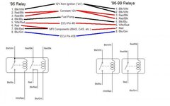
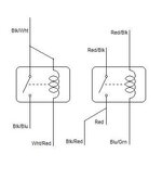
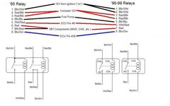
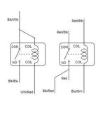
they come from a common source. (if you trace them about a foot up the harness, you'll see where they split.)
 
on your pics which ones are coils and no etc... I'm gona attempt this tonight

so I'll be deleting2 wires right?

the black with red stripe will tie into the solid red wire correct?

and the black white will split into 2 also correct?

if I'm looking at this right your diagram is upside down to this picture.?
You must be logged in to view this image or video.
 
OK, updated the pics with more info. :cool: 
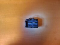
check out the new ones. also, I added another pic to help make the link between my images, and the actual relay(s) :hmm:

You must be logged in to view this image or video.


You must be logged in to view this image or video.


look down inside the relay plug, where the contacts are. it will all make sense :thumb:
You must be logged in to view this image or video.


Be sure to post your results about whether this worked or not for you. I have not been able to personally test this, it's all theory (no promises), so you'll have to let me know if this works for you.
 

Attachments

  • 95_vs_96+_MFI-FP_Relay.jpg
    95_vs_96+_MFI-FP_Relay.jpg
    36.9 KB · Views: 780
  • 95_wires-96+_relays.JPG
    95_wires-96+_relays.JPG
    12.8 KB · Views: 720
  • 2011-03-05 16.04.03.jpg
    2011-03-05 16.04.03.jpg
    22.5 KB · Views: 757
Support Vendors who Support the DSM Community
Boosted Fabrication ECM Tuning ExtremePSI Fuel Injector Clinic Innovation Products Jacks Transmissions JNZ Tuning Kiggly Racing Morrison Fabrications MyMitsubishiStore.com RixRacing RockAuto RTM Racing STM Tuned

Latest posts

Build Thread Updates

Vendor Updates

Latest Classifieds

Back
Top