Sniffbooger
Proven Member
- 315
- 139
- Apr 12, 2020
-
San Diego,
California
Hi all, my first post in a DSM forum, as I usually tinker with Hondas and Toyotas, but I bought my Eclipse GST with ideas of making a fun daily driver....it has a 6 bolt swap already installed but the previous owner didn't get it running very good and I bought it for cheap... so now I'm going thru it trying to address the issues.
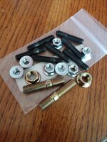
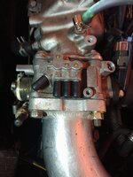
I was able to get it started after replacing the Engine Coolant Temp sensor and fixing some vacuum leaks. It still idles very rough and surges however. The exhaust smells rich. Exhaust leaks at the header. New exhaust studs coming soon. Two are stripped, and one is broken off... I removed and cleaned the VAF/MAF sensor with alcohol, but it may need replacing... Not tested yet...the 1g IPS sensor is acting as the throttle stop screw, not hooked up. May be in need of proper setting as a throttle stop.
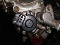
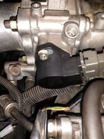
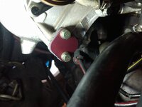
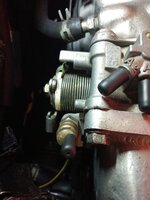
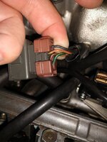
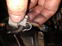
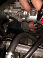
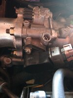
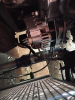
My main question is in regard to the ISC/IACV motor... It's a flat brown one with 3 screws and a 6prong connector. Does anybody know if this is a 1g Eclipse ISC? Or what year/model the lower throttle body and FIAV is from? Are the 1g/2g interchangeable?? I suspect it may be faulty, and I would rather have a newer black one... and if the fast idle air valve is bad, would I need to replace the entire lower throttle body assembly...any suggestions? Looking to make the car run/start more reliably. Thanks!
I was able to get it started after replacing the Engine Coolant Temp sensor and fixing some vacuum leaks. It still idles very rough and surges however. The exhaust smells rich. Exhaust leaks at the header. New exhaust studs coming soon. Two are stripped, and one is broken off... I removed and cleaned the VAF/MAF sensor with alcohol, but it may need replacing... Not tested yet...the 1g IPS sensor is acting as the throttle stop screw, not hooked up. May be in need of proper setting as a throttle stop.
My main question is in regard to the ISC/IACV motor... It's a flat brown one with 3 screws and a 6prong connector. Does anybody know if this is a 1g Eclipse ISC? Or what year/model the lower throttle body and FIAV is from? Are the 1g/2g interchangeable?? I suspect it may be faulty, and I would rather have a newer black one... and if the fast idle air valve is bad, would I need to replace the entire lower throttle body assembly...any suggestions? Looking to make the car run/start more reliably. Thanks!
You must be logged in to view this image or video.
You must be logged in to view this image or video.
You must be logged in to view this image or video.
Last edited:
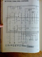
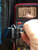
 ...So I'm going to view a couple of videos too and test it see if the movement is correct and also if my ECU drivers are functional.... I may order just the black ISC motor if needed. Hopefully this will cure some of the issues. Ill update as I go! Thank you for the nice diagnostic diagrams....and for replying! DSMtuners rocks!