The Top DSM Community on the Web

For 1990-1999 Mitsubishi Eclipse, Eagle Talon, Plymouth Laser, and Galant VR-4 Owners. Log in to remove most ads.

Please Support RTM Racing
Please Support STM Tuned

How to check piston to deck clearance

This site may earn a commission from merchant
affiliate links, including eBay, Amazon, and others.

This site may earn a commission from merchant affiliate links, including eBay, Amazon, and others.

BogusSVO

10+ Year Contributor
5,891
318
Jul 1, 2009
Pensacola, Florida
How to check piston to deck clearance

The subject is a Toyota 2ZZ

The block is being milled to ensure a good gasket sealing surface.

The short block must be dry assembled with crank, rods, and pistons.
Rod and main bearings are installed, and only the 2nd ring installed.

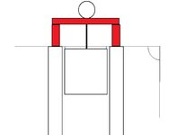
The tools used are a dial indicator and bridge stand

Now zero the dial indicator on the block with .100 preload.
You must be logged in to view this image or video.


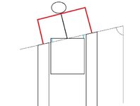
Next slide the dial indicator over the piston and rock the crank back and forth till the highest reading is found.
You must be logged in to view this image or video.


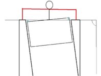
Now read the difference from zero to the depth of the piston.

In this case it was .004

It took .003 to square the block. Leaving the piston .001 in the bore at true TDC
 
Matt I may do that.. thanks for the tip on that How to.
 
How are you accounting for piston rock and the parallelism of the deck to the top of the piston?
 
the #2 ring is on the piston to limit piston rock.
 
Right, but there will still be some rock.. and how are you checking deck paralellism?

What I'm getting at is that the deck clearance on the intake side of the piston could be different than on the exhaust side of the piston. Unless the deck and bore axis have both been verified, the deck is not a truly accurate reference for measurement.
 
that would have to be checked from the center line of the crank main bore,

also due to the natural rock in a piston when it is running, what your asking about paralellism is going to alter in relation of the stoke the piston is going to alter.

when checking the P2D clearance you will try to keep to the center line of the wrist pin, insted of one side or the other, for that will have the lest amount of rock.

and that is not normally an issue, for the reason that the whole deck surface is machined at once
that would be an issue if you had to mill the surface down each side... ot the factory had a really bad set up when they first machined the block.

Automotive maching is "sloppy" when compaired to other forms of machine work, such as thats used in the aerospace indstry.
 
I think you still aren't understanding what I am trying to explain. I'm not sure if you are just unfamiliar with blueprinting a block..?..but I don't mean to offend or attack..

Everything you just said and the steps you have taken so far are meaningless if you don't at least measure or verify the blueprint dimensions of the block before you take reference measurements off of machined surfaces.
Also, the recession/protrusion of the piston needs to be measured at four points on the piston.. measuring just off the centerline of the wristpin does not give you enough data. You use the rock/average method on the thrust side and 180 to the thrust side, and measure directly at each end of the wrist pin axis. Keep all rings off the piston, and put your bridge on the thrust side of the piston. Rock the piston as far as it will rock in each direction, and then take the average of the min/max readings you get and that's your "P2D" on the thrust side of the piston. Repeat for the side 180 to the thrust. It doesn't matter how the piston rocks with the engine running, you still need to have a measurement for this part of the piston.

But.. before any of that, the vertical centerline of the bores must be verified at 90 degrees to the pan rail both longitudinally and latitudinally.. which is not hard to measure with two precision straight edges and a machinist protractor.

Then, the deck will need to be measured longitudinally against the main bores (which you mentioned), but you also need to measure the deck latitudinally against the bores and pan rails. If everything checks out okay so far, you can proceed to measure with the bridge on the deck, but if the deck is askew, you will need to surface it (with a BHJ "tru" style fixture) to make the deck true before you measure off of it. None of this has been accounted for with your method. For what it's worth, I've seen as much as .020" variance in block decks from the factory with various make blocks.

I drew up some pictures to illustrate my point by showing how measuring off of one point on top of the wrist pin means nothing if the bores and deck aren't true. The little blue lines are the discrepancies. The pictures are exaggerated a little bit... haha.. but drawn as if you were looking down the block through the main bores.
Automotive maching is "sloppy" when compaired to other forms of machine work, such as thats used in the aerospace indstry.
I also must say... granted, but I don't do any sloppy machine work. Cranks get ground with less than a couple tenths runout and size variance between journals, bores are honed to the tenth, valve guide clearance accurate to the tenth, wrist pin clearance and rod big end bores to the tenth, etc, among many other things.. definitely not "sloppy".
 

Attachments

  • deck1.jpg
    deck1.jpg
    16.8 KB · Views: 442
  • deck2.jpg
    deck2.jpg
    19.1 KB · Views: 455
  • bore.jpg
    bore.jpg
    21.3 KB · Views: 452
Last edited:
I do understand what you are saying.. and I would agree with you on an upper end build up, But 95% of the build ups being done do not need that much accuacy. Due to the extra time to take the measurements you talked of, the math involved, there fore the extra cost involved
this quick check is well enough, for when the "common" guy comes in and wants to run a MLS head gasket.

the oil pan rails make no diffrence tho. inles you flip the block over and measure the paralelle to the center line of the crank, and calculate the distortion of the pan rail

every thing is based of the centerline of the crank.

when the block is milled it is set on the mains on a round bar, then the deck to center like of the mains is set (as long as the round bar is machinist strait)
I have fond many blocks to be off due to tilt ot a re-align bore of the block.
 
Oh, I see. I guess I was just expecting a "how to" to involve more steps... but I still disagree.

You're right, 95% of the engines out there will run just fine without everything being done.. but I just can't stand cutting on a block without knowing everything first. If you spend 45 minutes one time and make the tools, you can check everything in a matter of minutes and the math is just one equation using the law of sines. Correcting the bore axis only involves an indicator on your boring bar head and shims under the block fixture. Whenever I get a block in that gets fully machined (line honed, bored, honed, surfaced) I check and correct for everything I mentioned and it only adds about 15 extra minutes max to the total machining time as opposed to doing it without.

The crank centerline is indeed a reference for measurement, but only in one axis (longitudinal). The pan rails are the datum that the factory uses for the bore axes, and the latitudinal alignment of the deck is referenced from the bore axis. That's why the fixturing for boring a v8 block has a precision bar through the mains along with a 45 degree wedge that the block sits on and inline blocks are just set on their pan rails on precision parallels. Any block that gets bored is fixtured from the pan rails. 90 degree v's have 45 degree banks, 60 degree v's have 30 degree banks, and inline blocks are supposed to be 0 degrees and these angles have to be referenced from somewhere.
The only time pan rails will be skewed a significant amount is if the block was severely overheated, and even then you can re-machine the pan rails using BHJ block-tru fixturing.
 
you ever run a old quickway boring bar?? the wedges you speak of do not exisit with thet.. a round bar gets placed thu the mains and then the head deck surface it air lifted to the bottom of the table.

then bore away...

I do not do alot of block/ lower end work on engines, I mainly deal with cylinder heads

I tend to keep the How tos simple, so guys that are not in the trade have a better idea of what is going to happen to there parts.

I would like to see your how to blueprint a block tho.
 
Yeah, I own a kwik way FN boring bar, and the only time I like to use it is when the deck of the block has either been verified or surfaced prior with a BHJ fixture. Otherwise, all blocks get surfaced in a Berco ACP151.

I am going to be building a stock 4g63 in a few weeks, I can get some pictures of my blueprinting tools and do an extensive blueprint write up.
 
Support Vendors who Support the DSM Community
Boosted Fabrication ECM Tuning ExtremePSI Fuel Injector Clinic Innovation Products Jacks Transmissions JNZ Tuning Kiggly Racing Morrison Fabrications MyMitsubishiStore.com RixRacing RockAuto RTM Racing STM Tuned

Latest posts

Build Thread Updates

Vendor Updates

Latest Classifieds

Back
Top