Okay guys I have put together some camshaft information I think that will help all of us to understand the camshaft and its operation better. This will help us to really know what we need to look for when chosing a cam")
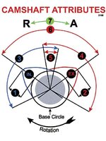
Camshaft Attributes
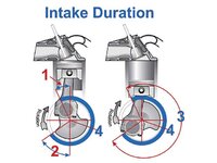
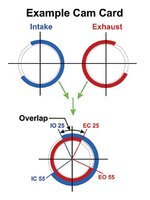
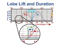
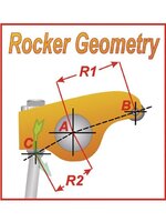
1. Intake lobe lift, 2. Exhaust lobe lift, 3. Intake duration, 4. Exhaust duration, 5. Overlap, 6. Lobe Centerline Angle (LCA), 7. Cam Advance (A) and Retard (R). View Related Article
Camshaft Attributes
1. Intake lobe lift, 2. Exhaust lobe lift, 3. Intake duration, 4. Exhaust duration, 5. Overlap, 6. Lobe Centerline Angle (LCA), 7. Cam Advance (A) and Retard (R). View Related Article