The Top DSM Community on the Web

For 1990-1999 Mitsubishi Eclipse, Eagle Talon, Plymouth Laser, and Galant VR-4 Owners. Log in to remove most ads.

Please Support Rix Racing
Please Support STM Tuned

Street Build 1g build - The Real Life Trials and Tribulations of building a DSM

This site may earn a commission from merchant
affiliate links, including eBay, Amazon, and others.

This site may earn a commission from merchant affiliate links, including eBay, Amazon, and others.

Think of it this way, mitsu sold shims in 0.001" increments and made a bazillion of each one and those still sell for $9-25 EACH!

I have 1x MD706574 - 0.0516" input shaft shim in stock. $23.53

I have only a MD712349 - 0.0527" intermediate shaft shim in stock. $11.56.

$9.10 s/h USPS small flat rate box.

$44.19 shipped.
Good point..

Alrighty! I'll message you
 
So lots has happened.
I snagged those shims from Tim from the previous post. They'll give slightly less preload than i truly want but i should be okay for what i plan to do with that stock trans.

My Wheel front wheel bearings and seals showed up, just waiting on getting my hubs, calipers, Knuckles back from blasting so i can paint it all. Probably just black. I snagged some self etching primer to make sure it sticks better as well.

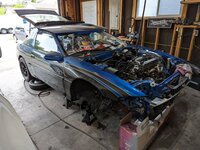
My front Quarter panels have been laying either leaned up against my garage door, or laying in the hatch of the Talon so I decided i would lightly install them. Just a few bolts holding them on. Man what a difference it makes to the car!
PXL_20230601_234000359.jpg

Modified my clear cam gear cover so that it would fit with the big AN fuel line, fits good. This will get replaced someday since the cam gear bolt holes are not centered over the bolts. I must have had my eyes crossed when i cut them out LOL
PXL_20230602_004701484.jpg

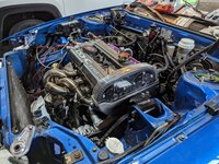
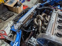
I got an itch to make the car look more complete so I installed some stuff. Crank pulley, alternator belt, Intake manifold, Radiator, radiator hoses and plug wires just to see how this was all coming together and maybe its just the missing transmission but the scheme of everything doesnt really seem to fit together. I havent tried too hard to make everything match so thats probably why.
PXL_20230602_011917522.jpgPXL_20230602_011923959.jpgPXL_20230602_012000510.jpg

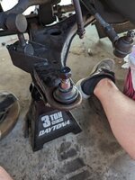
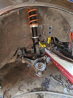
Went ahead and replaced the driver side front lower ball joint, pretty simple process this time. Popped out with 2 smacks of a hammer and pressed in nicely. I fought the snap ring again but it took me much, much less time to get it in this time.
PXL_20230602_224813068.jpg

I've ordered up some new rotors and pads. I went with some R1 concepts drilled and slotted for the front, and then just some powerstop blanks for the rear. To top it all off, I went with some EBC Yellowstuff pads for all 4 corners so that should give me plenty of stopping power. EBC claims they bite good in the cold and without being warmed up so i guess we'll see.

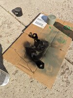
also ordered up some braided stainless steel brake lines as well to replace the rubber hoses. Should stiffen up the braking a little bit more as well. I then wire wheeled the brake line brackets and then painted them with the self etching primer and then low gloss black as i plan to re-use them to hopefully mount the braided lines and didnt want them to look awful. They were pretty surface rusted, if not a little actually rusting.
PXL_20230602_234104177.jpg

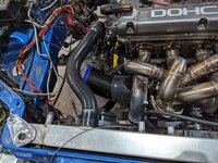
My brother came over yesterday as well to help me trim my carbon fiber turbo inlet/intake. It was too long and at too much of an angle to be able to fit any good flowing filter below the hood line. We made some poorly calculated measurements and boom, it worked. Basically just cut the inlet right int he middle of the bend so that it removed some of the angle out of the bend and then threw on a filter. Should stick the filter right into the factory location, just damn close to it.
PXL_20230603_020609479.jpgPXL_20230603_020612392.jpg

This is a big one and I cannot believe I didn't catch this sooner.
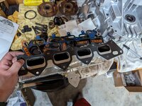
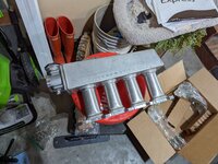
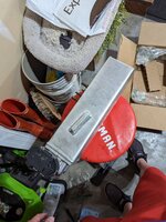
This Magnus SMIM ive had for like 2 years now.. it was sold to me stating it was for a 6 bolt head and i dont know why i just believed them but I was showing my brother while he was over here the Phenolic gasket and thought "Man these ports sure look small" and wouldnt you know it ITS FOR A 7 BOLT.. So now its time to sell this one and buy another manifold. Its a good thing that i hadnt started making anything for the intercooler piping.
PXL_20230603_015103803.jpg
I put it up for sale on Facebook at about 10 pm yesterday and i woke up to 7 messaged from people wanting to buy it. I listed it for $400 and its now sold :)
I used that to buy a JFM Race manifold! (actually for a 6 bolt)

here's to working on cars! 🍻🥴🫠
 
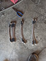
Brake lines showed up, they were overnighted from the east coast (with their standard flat rate shipping). SHOUT OUT TO JNZ!
These look great and they utilize the stock mounting brackets on the coil overs which is really cool. I i cant seem to find out these are supposed to be installed. There's 2 longer female-female lines, 2 longer female-male lines, and 4 shorter female-male lines. JNZ said that they install the same way the factory lines came off, I haven't gotten back around to looking at the old ones to see how they were.
PXL_20230606_005133970.jpgPXL_20230606_005234692.jpg

Wheel bearings, seals, and Shims from Tim showed up.

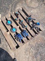
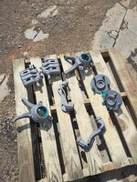
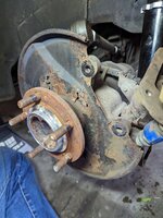
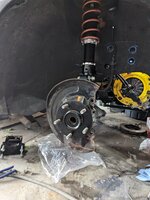
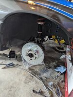
Dropped off the brakes, hubs, and Knuckles all to be blasted. These turned out great.
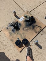
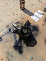
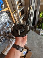
I Blew them off with compressed air and coated them with self etching primer and then painted them all a low gloss black from duplicolor. I was REALLY unsure about the hubs being black but after putting the wheels on i think it'll be okay.
received_202813328892279.jpegreceived_160202373695699.jpegPXL_20230604_223033497.jpgPXL_20230604_223036932.jpgPXL_20230605_001631905.jpg

I got the bearings pressed into the knuckles pretty easily, the freaking snap rings took me forever to get in. I really hope I never have to touch those again. The rear seal as well.
PXL_20230606_001606730.jpg

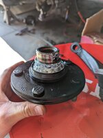
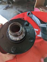
I installed the outside wheel seal on the hub, and then pressed on the inner race onto the hub also, and noticed that the seal had a lip that protruded into the race where the bearing would ride on the race. I confirmed on rockauto that this is the right seal number and location however i think its just the wrong type of seal. I ordered up some new OEM ones from JNZ to make sure that i get the right ones .
I had to cut the lip off that one seal to get the race off. I did try to flip the 2nd seal meant for the other side so that the lip was facing towards the hub but it doesn't seat down all the way. These are definitely not the right seals for the outside.
PXL_20230605_233825373.jpgPXL_20230605_233827706.jpg

Last night I was get feeling froggy and tried to get my trans re-assembled. It did not go well. I got it mostly together, lower case, mid case and then was working on the 5th gear/reverse hub and realized that the shift fork needs installed on the hub/slider first and then both slide onto the shift rail. i started to do that and then realized that i needed the 5th gear intermediate gear installed... so i had to pull the 5th gear off the hub to install the intermediate gear. After I got that one on i decided to maybe install the viscous coupler, which i went to do and found out that i lost the retaining ball :(. While i was looking for it I found one of the shims that time sent me unopened on my bench.... it was for the input shaft bearing. Obviously this needs installed. So back apart it came. After i got that installed again and touched up the areas of RTV that needed it I got back to putting on the 5th gear stuff with the fork installed and I just could not get the holes in the rail and the fork to line up. The rail kept spinning counter clockwise everything i tried to Test shift into 5th/reverse.. I messed with this for quite some time to try and figure it out but couldn't. Back apart the trans came again so i could check it out. The selector kept hitting the side of the rail for 5th and rotating it so that the holes wont line up.
I found the coupler retaining ball!

Right now the trans is back where i started with all the RTV cleared off waiting to be re-installed.. again.
 
Last edited:
Evening update

I was able to get the trans about 98% done. The end cover is on and torqued to spec to let the RTV seal. All that's needing installed is the output shaft, viscous coupler and the 2 nuts.

I'll probably get that done quick by the end of the week and then work on getting the trans in the car late next week
PXL_20230608_011104115.jpg
 
Evening update

I was able to get the trans about 98% done. The end cover is on and torqued to spec to let the RTV seal. All that's needing installed is the output shaft, viscous coupler and the 2 nuts.

I'll probably get that done quick by the end of the week and then work on getting the trans in the car late next week
View attachment 698243
If you ever do this a bunch buy a box of washers and you don't have to bolt the end cover on to set the rtv on the other pieces.
 
Im not understanding why this would help LOL I've reread it about 5 times now.

Is it just a set it on top type of thing or?
So you can go ahead and install the output shaft, nuts and viscous and dont have to wait. You also have to have the end case off to do all that. Thisbis how you would bolt it down so you don't break any other seals before doing the final end case.
 
So you can go ahead and install the output shaft, nuts and viscous and dont have to wait. You also have to have the end case off to do all that. Thisbis how you would bolt it down so you don't break any other seals before doing the final end case.
Ahh okay now I'm catching on. That would be really useful actually.
 
Be extremely careful doing it this way, as you do not have the case supported and are putting load on the output shaft which will push the bearing plate up and separate the RTV bond. You should have done the bearing plate RTV to gear cluster case section on both sides of contact to each other, then installed 5th intermediate, then viscous coupler and detent ball and snap ring since you have to pound it down with a little jiggle to align the 2 sets of splines while putting upward hand pressure on the output shaft (i use a spare viscous coupler or chunk of wood around the same thickness and a prybar to put a load i can modulate so it retains the detent ball in proper alignment during viscous coupler install). Then I install a lubed up 5th input needle bearing, lubed 5th gear (lube bore and synchro cone), then lubed 5th synchro, add a bit more lubed and install 5th/Rev hub and slider assembly with synchro keys aligned and 5th/Rev shift fork and then reverse synchro, then shaft nuts, put hand pressure on Rev synchro and shift into reverse, install 5th/Rev shift fork roll pin, torque end shaft nuts, shift to neutral and stake shaft nuts. Then its just adding a bit more lube to the input shaft and reverse side, install reverse wave spring, align cover to make sure the oil guide doesn't get jammed up on the 5th gear cover oil guide and damage it, install cover and torque bolts to 29 ft/lb in star pattern. When you do it all quick at once with the rest of the build it is easier to have the cover bolts bonded in with rtv. Now you have to deal with the long ones going all the way through and potentially causing a leak at the gear cluster case section.
 
Do you still need help with how to install the JNZ Tuning brake lines? I just installed mine and I can take pictures. You use the long female to female lines for the upper portion of the line, and the male to female for the bottom. You reuse the stock S shaped metal line to connect the two. It'll be easier to see if you need a picture.
 
Do you still need help with how to install the JNZ Tuning brake lines? I just installed mine and I can take pictures. You use the long female to female lines for the upper portion of the line, and the male to female for the bottom. You reuse the stock S shaped metal line to connect the two. It'll be easier to see if you need a picture.
😐 I cut that small hardline.

That would explain why I can't get them to fit. 🫠
 
😐 I cut that small hardline.

That would explain why I can't get them to fit. 🫠

Don't feel bad. I legit almost did the same exact thing until I looked a little harder at it. I have to believe someone out there has those hardlines just chilling in their scrap pile or spare shell they could sell for cheap. If someone could confirm if the 1G N/T's have identical lines I'll go yank some from the local scamyard.
 
Be extremely careful doing it this way, as you do not have the case supported and are putting load on the output shaft which will push the bearing plate up and separate the RTV bond. You should have done the bearing plate RTV to gear cluster case section on both sides of contact to each other, then installed 5th intermediate, then viscous coupler and detent ball and snap ring since you have to pound it down with a little jiggle to align the 2 sets of splines while putting upward hand pressure on the output shaft (i use a spare viscous coupler or chunk of wood around the same thickness and a prybar to put a load i can modulate so it retains the detent ball in proper alignment during viscous coupler install). Then I install a lubed up 5th input needle bearing, lubed 5th gear (lube bore and synchro cone), then lubed 5th synchro, add a bit more lubed and install 5th/Rev hub and slider assembly with synchro keys aligned and 5th/Rev shift fork and then reverse synchro, then shaft nuts, put hand pressure on Rev synchro and shift into reverse, install 5th/Rev shift fork roll pin, torque end shaft nuts, shift to neutral and stake shaft nuts. Then its just adding a bit more lube to the input shaft and reverse side, install reverse wave spring, align cover to make sure the oil guide doesn't get jammed up on the 5th gear cover oil guide and damage it, install cover and torque bolts to 29 ft/lb in star pattern. When you do it all quick at once with the rest of the build it is easier to have the cover bolts bonded in with rtv. Now you have to deal with the long ones going all the way through and potentially causing a leak at the gear cluster case section.
Thanks for the advice Tim! I'll. Definitely try to apply these going forward.

I wanted to note that I do not have the output shaft installed yet either
 
Be extremely careful doing it this way, as you do not have the case supported and are putting load on the output shaft which will push the bearing plate up and separate the RTV bond. You should have done the bearing plate RTV to gear cluster case section on both sides of contact to each other, then installed 5th intermediate, then viscous coupler and detent ball and snap ring since you have to pound it down with a little jiggle to align the 2 sets of splines while putting upward hand pressure on the output shaft (i use a spare viscous coupler or chunk of wood around the same thickness and a prybar to put a load i can modulate so it retains the detent ball in proper alignment during viscous coupler install). Then I install a lubed up 5th input needle bearing, lubed 5th gear (lube bore and synchro cone), then lubed 5th synchro, add a bit more lubed and install 5th/Rev hub and slider assembly with synchro keys aligned and 5th/Rev shift fork and then reverse synchro, then shaft nuts, put hand pressure on Rev synchro and shift into reverse, install 5th/Rev shift fork roll pin, torque end shaft nuts, shift to neutral and stake shaft nuts. Then its just adding a bit more lube to the input shaft and reverse side, install reverse wave spring, align cover to make sure the oil guide doesn't get jammed up on the 5th gear cover oil guide and damage it, install cover and torque bolts to 29 ft/lb in star pattern. When you do it all quick at once with the rest of the build it is easier to have the cover bolts bonded in with rtv. Now you have to deal with the long ones going all the way through and potentially causing a leak at the gear cluster case section.
You make my head hurt LOL. Yah I will definitely being paying (you) hopefully to rebuild my trans. Kudos to those taking this on without someone teaching them the ropes first.
 
Be extremely careful doing it this way, as you do not have the case supported and are putting load on the output shaft which will push the bearing plate up and separate the RTV bond. You should have done the bearing plate RTV to gear cluster case section on both sides of contact to each other, then installed 5th intermediate, then viscous coupler and detent ball and snap ring since you have to pound it down with a little jiggle to align the 2 sets of splines while putting upward hand pressure on the output shaft (i use a spare viscous coupler or chunk of wood around the same thickness and a prybar to put a load i can modulate so it retains the detent ball in proper alignment during viscous coupler install). Then I install a lubed up 5th input needle bearing, lubed 5th gear (lube bore and synchro cone), then lubed 5th synchro, add a bit more lubed and install 5th/Rev hub and slider assembly with synchro keys aligned and 5th/Rev shift fork and then reverse synchro, then shaft nuts, put hand pressure on Rev synchro and shift into reverse, install 5th/Rev shift fork roll pin, torque end shaft nuts, shift to neutral and stake shaft nuts. Then its just adding a bit more lube to the input shaft and reverse side, install reverse wave spring, align cover to make sure the oil guide doesn't get jammed up on the 5th gear cover oil guide and damage it, install cover and torque bolts to 29 ft/lb in star pattern. When you do it all quick at once with the rest of the build it is easier to have the cover bolts bonded in with rtv. Now you have to deal with the long ones going all the way through and potentially causing a leak at the gear cluster case section.
So, question. I got the output shaft in, viscous coupler on, snap ring and there seems to be some in and out play of the output shaft/pinion. Is that right?? Here's a video

 
Got some more done the last few days.

As @CrackedDSM said, I'm missing the hardline for the front brakes. TMZ actually has them brand new for $15 for the set. Ordered those up, should be here Monday.

Outer wheel seals came in and I was able to get the hubs pressed into the knuckles finally. I actually greased the bearings more with some other heavy duty lithium grease. I've forgotten the name of it but I'll update it later. After I got everything pressed together the hubs were REALLY hard to turn.. after I got it to spit a few times it got easier and easier and how they turn pretty well. Not flopping around or anything, or spinning freely. Just nice and controlled. PXL_20230610_002023164.jpgPXL_20230610_002001500.jpg

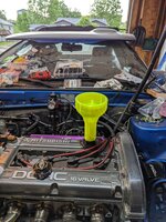
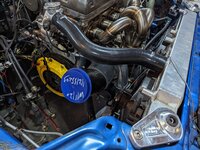
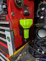
I snagged one of these really cool 3d printed tunnels with a breather on it. This kind snaps twists into the oil cap location just like OEM! Went for bright green because why not.

PXL_20230609_215507965.jpgPXL_20230609_215354662.jpg

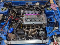
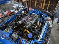
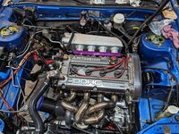
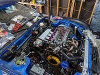
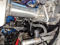
New manifold showed up and... It's enormous. I had no clue these were this big. No issues, the throttle body bolted on and it clears everything in the engine bay thankfully.

PXL_20230609_223542843.jpgPXL_20230609_223548102.jpgPXL_20230609_224555640.jpgPXL_20230609_224603311.jpg
Later during the week I spent a few minutes getting the viscous coupler and output shaft installed. I noticed a pretty good about of in and out play of the output shaft after I got everything installed. I asked Tim in my last post if it was normal no answers yet but I hope that it's okay. It's supposed to have preload on it and if it's got play that means no preload.

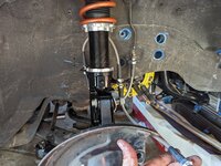
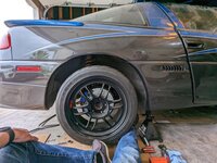
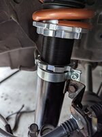
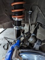
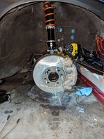
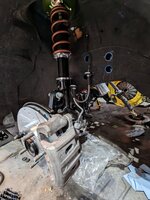
Today I did some more brake stuff. Focused more on getting the rears done. Replaced the soft lines with the new hard lines and removed the old pads. Unfortunately my EBC brake pads haven't showed up yet (they're late) so I couldn't finish the rears completely but they're basically ready. I also found a solution/ workaround for the shitty brake line clamps that come with the rears of the Feal coilovers. I actually cut up a spare coupler and used a small 1/4 x 1/2" section of it inside the clamp and then tightened it down and perfect! It's solid as a rock. I threw the rear and front rotors on (apparently I ordered drilled and slotted for the rears too) and the fronts I got the brake lines installed minus the crossover hardline.

Rears:
PXL_20230611_001603833.jpgPXL_20230611_002205098.jpgPXL_20230611_002339299.jpg
Found that the driver rear brake dust cover was rusted. First bit of rust I've found on this car actually.
PXL_20230611_004749183.jpg

Fronts
PXL_20230611_020755059.jpgPXL_20230611_021732422.NIGHT.jpg


Last little Thing was a I made a mounting point for the injector harness as a strain relief. Using one of the manifold bolts as a mounting point and one of the rubber clamps. Seems to be fine!
PXL_20230611_012802572.jpg
 
Hell yeah, good deal.

Have you ridden with those FEALs yet? How’s the ride quality? Should I make a dentist appointment for new fillings every time I hit a pot hole or is it nice and smooth?

I’m wanting coilovers eventually but there’s like four or five ones to choose from. The $2k coilovers from Flatout I’ve heard are the best but that’s super steep. No experience with the Megan’s or the others though.
Honestly I have no clue car has been on jack stands since I got them installed.

I did a bunch of research and they were the best bang for your buck in that price range.

I had some flatout sr52s for my Sti and they worked well for a while. Like most coilovers they seized too. I think one of the struts also ended up going out too after about a year.
 
Well allow me to answer my own question about the output shaft play.

I forgot the lower outter race for the center diff.
I guess this serves as a lesson to take your time and stay organized. Especially when doing big projects.

Race found, cleaned installed and everything is back in again and waiting for the one side of the bearing case to seal again.

PXL_20230611_220609424.jpg
 
Well allow me to answer my own question about the output shaft play.

I forgot the lower outter race for the center diff.
I guess this serves as a lesson to take your time and stay organized. Especially when doing big projects.

Race found, cleaned installed and everything is back in again and waiting for the one side of the bearing case to seal again.

View attachment 698618
How did you shim it without a lower race?
 
Support Vendors who Support the DSM Community
Boosted Fabrication ECM Tuning ExtremePSI Fuel Injector Clinic Innovation Products Jacks Transmissions JNZ Tuning Kiggly Racing Morrison Fabrications MyMitsubishiStore.com RixRacing RockAuto RTM Racing STM Tuned

Latest posts

Build Thread Updates

Vendor Updates

Latest Classifieds

Back
Top