MattHDSM
5+ Year Contributor
- 113
- 71
- Oct 20, 2018
-
Ottawa,
ON_Canada
Hello DSMers!
I've recently been pondering the idea of having a dedicated single key switched race mode for my talon. I know to some extent that this could be accomplished by using ecmlink's secondary maps setting via the idle switch or custom FPS/EGR settings. Part of any good race mode would be enabling NLTS, but (as far as I'm aware) that means NLTS stays active on street mode as well, unless I open link and turn it off again. Now I can hear you guys saying, "just leave NLTS on", or "it's not a big deal to turn NLTS on or off using link", but I like the gimmick of having a dedicated switch for racing! I think I have come up with a wiring setup in which NLTS can stay enabled in link (and keeps cruise control), but can be effectively toggled on or off using a physical switch instead. Below is an animated gif of my diagram which hopefully makes it a little easier to follow, but I have also attached each individual example as well. The light gray arrows show the direction of current flow by the way.
Note - I didn't use any specific Double Pole Double Throw (DPDT) relay because the pinout could differ depending on the relay being used so keep that in mind.
What I Know Via Service Manual Wiring Diagrams:
In the factory wiring setup with cruise control, the cruise control ECU (pin connected via a black/red wire) wants to see ground to disable cruise control. One way the ECU disables cruise control is by using the upper clutch pedal position sensor. When the clutch pedal is pressed in, the clutch pedal position sensor closes the circuit and is connected to ground. Cruise control is disabled.
What I Know Via ECMTuning:
To my understanding, when NLTS is active via link, Pin 91 on the ECU wants to see ground and this is accomplished via the same clutch pedal position sensor closing the circuit and connecting the pin to ground. This can be read about here.
How The Clutch Cut Wire Is Normally Used (w/ Cruise Control):
To use NLTS, the ECMLink clutch cut wire is spliced in between the cruise control ECU and the clutch pedal position sensor via the black/red wire. The short orange wire splices into the cruise control ECU, the violet wire splices into the clutch pedal position sensor, and the long orange wire splices into Pin 91 of the main ECU. Please see gofer's thread on installing NLTS here if you need more information on how to normally install the clutch cut wire while keeping cruise control.
How I Think My Diagram Works:
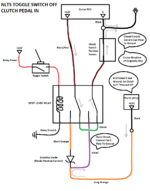
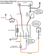
With the switch toggled off, the wiring is essentially the same as the factory wiring. Current flows from the cruise control ECU into the relay, through the green wire, and into the clutch pedal position sensor. The green wire is a jumper between the two pins on the relay which reconnect both ends of the black/red wire. If the clutch pedal is pressed in, the circuit is closed and current travels to ground, disabling cruise control if it was active. If the clutch pedal is not pressed in, the circuit is open and current cannot flow to ground. Meanwhile, Pin 91, doesn't see ground because that circuit is also open and NLTS does not activate. This is no different than the normal clutch cut wiring because while the clutch is out (not pressed), the circuit is open so NLTS does not activate either.
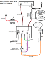
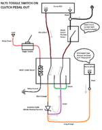
With the switch toggled on, the wiring is essentially the same as the normal clutch cut wiring. Current flows from the cruise control ECU into the relay, through the short orange wire, through the diode, through the violet wire, and back through the relay to the clutch pedal position sensor. Meanwhile, current flows from Pin 91, through the long orange wire, the current is blocked by the diode and flows through the violet wire, and back through the relay to the clutch pedal position sensor. If the clutch pedal is pressed in, the circuit is closed and current travels to ground, disabling cruise control if it was active (Why is your cruise control on??? You're in race mode!!!), and activating NLTS. If the clutch pedal is not pressed in, the circuit is open and current cannot flow to ground. Pin 91 doesn't see ground because that circuit is also open and NLTS does not activate.
Sorry about the length! If anybody has any feedback, or I'm horribly wrong with how this would work, please let me know! I unfortunately cannot test this myself right now, but I am hoping I can implement it for next summer.
I've recently been pondering the idea of having a dedicated single key switched race mode for my talon. I know to some extent that this could be accomplished by using ecmlink's secondary maps setting via the idle switch or custom FPS/EGR settings. Part of any good race mode would be enabling NLTS, but (as far as I'm aware) that means NLTS stays active on street mode as well, unless I open link and turn it off again. Now I can hear you guys saying, "just leave NLTS on", or "it's not a big deal to turn NLTS on or off using link", but I like the gimmick of having a dedicated switch for racing! I think I have come up with a wiring setup in which NLTS can stay enabled in link (and keeps cruise control), but can be effectively toggled on or off using a physical switch instead. Below is an animated gif of my diagram which hopefully makes it a little easier to follow, but I have also attached each individual example as well. The light gray arrows show the direction of current flow by the way.
You must be logged in to view this image or video.
Note - I didn't use any specific Double Pole Double Throw (DPDT) relay because the pinout could differ depending on the relay being used so keep that in mind.
What I Know Via Service Manual Wiring Diagrams:
In the factory wiring setup with cruise control, the cruise control ECU (pin connected via a black/red wire) wants to see ground to disable cruise control. One way the ECU disables cruise control is by using the upper clutch pedal position sensor. When the clutch pedal is pressed in, the clutch pedal position sensor closes the circuit and is connected to ground. Cruise control is disabled.
What I Know Via ECMTuning:
To my understanding, when NLTS is active via link, Pin 91 on the ECU wants to see ground and this is accomplished via the same clutch pedal position sensor closing the circuit and connecting the pin to ground. This can be read about here.
How The Clutch Cut Wire Is Normally Used (w/ Cruise Control):
To use NLTS, the ECMLink clutch cut wire is spliced in between the cruise control ECU and the clutch pedal position sensor via the black/red wire. The short orange wire splices into the cruise control ECU, the violet wire splices into the clutch pedal position sensor, and the long orange wire splices into Pin 91 of the main ECU. Please see gofer's thread on installing NLTS here if you need more information on how to normally install the clutch cut wire while keeping cruise control.
How I Think My Diagram Works:
With the switch toggled off, the wiring is essentially the same as the factory wiring. Current flows from the cruise control ECU into the relay, through the green wire, and into the clutch pedal position sensor. The green wire is a jumper between the two pins on the relay which reconnect both ends of the black/red wire. If the clutch pedal is pressed in, the circuit is closed and current travels to ground, disabling cruise control if it was active. If the clutch pedal is not pressed in, the circuit is open and current cannot flow to ground. Meanwhile, Pin 91, doesn't see ground because that circuit is also open and NLTS does not activate. This is no different than the normal clutch cut wiring because while the clutch is out (not pressed), the circuit is open so NLTS does not activate either.
With the switch toggled on, the wiring is essentially the same as the normal clutch cut wiring. Current flows from the cruise control ECU into the relay, through the short orange wire, through the diode, through the violet wire, and back through the relay to the clutch pedal position sensor. Meanwhile, current flows from Pin 91, through the long orange wire, the current is blocked by the diode and flows through the violet wire, and back through the relay to the clutch pedal position sensor. If the clutch pedal is pressed in, the circuit is closed and current travels to ground, disabling cruise control if it was active (Why is your cruise control on??? You're in race mode!!!), and activating NLTS. If the clutch pedal is not pressed in, the circuit is open and current cannot flow to ground. Pin 91 doesn't see ground because that circuit is also open and NLTS does not activate.
Sorry about the length! If anybody has any feedback, or I'm horribly wrong with how this would work, please let me know! I unfortunately cannot test this myself right now, but I am hoping I can implement it for next summer.