The Top DSM Community on the Web

For 1990-1999 Mitsubishi Eclipse, Eagle Talon, Plymouth Laser, and Galant VR-4 Owners. Log in to remove most ads.

Please Support STM Tuned
Please Support ExtremePSI

1G Oddly grouped ground wires to ECU

This site may earn a commission from merchant
affiliate links, including eBay, Amazon, and others.

This site may earn a commission from merchant affiliate links, including eBay, Amazon, and others.

Uncle Jacks Hands

Proven Member
64
7
Sep 10, 2019
Fairfax, Virginia
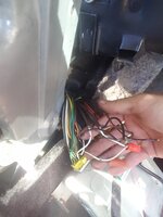
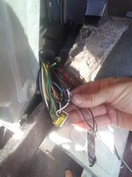
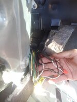
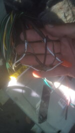
I discovered a couple ground wires that look to be tied together very oddly on my ecu. It looks like two of them (these two are the non coated silver ones) were connected to both the white wire for the O2 sensor (pin4) and the det sensor (pin 9) tied together along with 2 other black wires one from the o2 sensor loom and the other from somewhere else, and lastly there is a lone back with red stripe wire hanging out trimmed to the same length but not attached. Any insight on these wires and whether they need to be attached to anything? The only open pin whole in the ECU is the ABS pin 11. I will post the pictures from my phone right after this. I appreciate the help!
 

Attachments

  • 20190918_135709.jpg
    20190918_135709.jpg
    514.4 KB · Views: 106
  • 20190918_135735.jpg
    20190918_135735.jpg
    533.6 KB · Views: 115
  • 20190918_135636.jpg
    20190918_135636.jpg
    483.4 KB · Views: 111
  • 20190918_135629.jpg
    20190918_135629.jpg
    1 MB · Views: 108
Looks like someone was trying or did have something added in picking on the signals from those wires. Just reconnect them according to the factory schematic
 
The two wires (cables) that have a white wire, a black wire, and a silver shield coming out of them are for the engine sensors.

The two white wires run into the ecu. They are for the signal. The black wires tie together and are spliced (the grey tape with a clear plastic sleeve is factory) to go to the ecu “sensor ground” pin.

The fact that your white wire was nutted back together looks like a previous owner disconnected the sensor (generally it is the rear O2) to connect a gauge routed input into the ecu.

It would be better to solder that splice, rather than risk the cap from coming loose, but at least it looks to be connected correctly.
 
Thank you for the responses. Yes I agree about soldering, I am just waiting until I get everything dialed in and finalized before I do the finishing touches on the wiring. So just to confirm that everything there looks ok and it is nothing I need to concern myself with. Even with the non connected black wire with red striped? Thank you for your help.
 
Black with Red tracer is going to be power to the ecu, both on pin #12 and pin #25. Check it with a volt meter first, both with the ignition Off, and then with the ignition On.

Check your ecu plug and see if one of those wires is missing or clipped off.
 
So yeah, I was referencing the pinout sheet the whole time, Its just odd there isn't any open pins or doesn't look like anything missing on the plug side. Its just a couple ground wires then another black wire with red striping that I cant figure out where it comes from or where it is supposed to be attached.
 
Support Vendors who Support the DSM Community
Boosted Fabrication ECM Tuning ExtremePSI Fuel Injector Clinic Innovation Products Jacks Transmissions JNZ Tuning Kiggly Racing Morrison Fabrications MyMitsubishiStore.com RixRacing RockAuto RTM Racing STM Tuned

Latest posts

Build Thread Updates

Vendor Updates

Latest Classifieds

Back
Top