The Top DSM Community on the Web

For 1990-1999 Mitsubishi Eclipse, Eagle Talon, Plymouth Laser, and Galant VR-4 Owners. Log in to remove most ads.

Please Support Rix Racing
Please Support Morrison Fabrication

1G Auto swap update....

This site may earn a commission from merchant
affiliate links, including eBay, Amazon, and others.

This site may earn a commission from merchant affiliate links, including eBay, Amazon, and others.

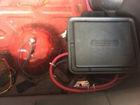
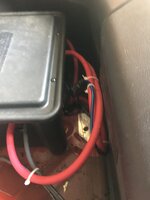
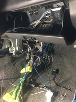
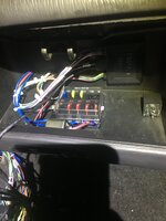
Distribution block to fuse box is fine.
ok so ill just use an external fuse to the switch. Thank you sir. I love building engines, mechanical shit......I like wiring as much as I like installing the waterpump pulley when the engine is installed in the chassis. HATE IT.....So tedious
 
It was a lot easier when I was 16.... speaker wire, some duct tape or masking tape. Sure it would short out periodically....Much easier.
 
A little late, but I would recommend that you run a larger than 2awg wire front to rear run. Then use fused distribution blocks on either end. 0/1 wire would be the minimum that I would use for any battery relocation project.

I'd also stay away from using those AGU glass fused blocks. They don't like the heat of the engine bay & I've seen plenty of them turn into resistors with enough heat cycles and/or age... they are basically made of a three piece construction that are all cold-soldered together. If you stick to a solid fuse construction type (like Maxi or ANL for the larger current runs) & you won't have any issues.

If you retained the factory 1g fuse block on the front passenger fender, then you can use the factory 80A Alternator fuse holder as a mini distribution block, provided that you use slightly longer 10mm bolts to secure the thicker 4awg ring terminals to it. I ran 4awg from my Saturn Alt to this location, and then on the other side to the fuse holder, added another 4awg run that went to the 0/1 distribution block that I've got under the hood. That 80A factory fuse can be upgraded at the same (the bolts need to be removed on either side in order to remove it)... I'm running a 120A fuse in this location.

Lastly, please choose another ground point. The three tiny spot welds on the rear spare tire retaining nipple are serving as your entire chassis ground right now. -You're better off running it up to the rear passenger side strut tower, where you will find a much more suitable ground (ie thicker/more plies of chassis to serve as a better conductor)

Wire in a relay for your fuel pump that gets triggered from the factory fuel pump wire (85). Pin 86 then goes to ground. Then run a fused (I used a single 15A fuse for my 450LPH Walbro pump) 12awg or larger sized wire to the N.O. relay position (87). Then pin 30 goes to the fuel pump directly.
What i ended up with...... ditched the 2 gauge for 0 gauge from the switch to the battery and from the switch to the distribution block. I ran a dedicated 2 gauge wire from the alternator to one side of the switch. The distribution block has 4 4 gauge ports i used for the small fuse box and the fuse box on the passenger side. The battery Is fused with a 150 amp fuse, my alternator with a 80 amp seeing as its the factory auto 75 amp. As far as the ground. I kept one as is and ran one up to the rear seatbelt mount. One 4 gauge to spare mount and one 0 gauge to the belt mount. I still think this is alittle overkill but. The only other question i had was grounding in the engine bay. I made a twin 4 gauge cable that bolts on to the tranny/ engine bolt and have one lead going to firewall and the other the passenger side fender wall.
 

Attachments

  • 8F0CBB26-D33E-48F5-94FF-C3FD59CA83AC.jpeg
    8F0CBB26-D33E-48F5-94FF-C3FD59CA83AC.jpeg
    266.6 KB · Views: 62
  • CCEDC0D4-8F11-4F1C-8735-0B05FD68C574.jpeg
    CCEDC0D4-8F11-4F1C-8735-0B05FD68C574.jpeg
    264.5 KB · Views: 64
  • EBC00136-EC99-4E38-8573-6E643F2E99E8.jpeg
    EBC00136-EC99-4E38-8573-6E643F2E99E8.jpeg
    293 KB · Views: 65
What i ended up with...... ditched the 2 gauge for 0 gauge from the switch to the battery and from the switch to the distribution block. I ran a dedicated 2 gauge wire from the alternator to one side of the switch. The distribution block has 4 4 gauge ports i used for the small fuse box and the fuse box on the passenger side. The battery Is fused with a 150 amp fuse, my alternator with a 80 amp seeing as its the factory auto 75 amp. As far as the ground. I kept one as is and ran one up to the rear seatbelt mount. One 4 gauge to spare mount and one 0 gauge to the belt mount. I still think this is alittle overkill but. The only other question i had was grounding in the engine bay. I made a twin 4 gauge cable that bolts on to the tranny/ engine bolt and have one lead going to firewall and the other the passenger side fender wall.

Ah.. I'm running a relocated & re-wound Saturn Alt (thus the larger 120A fuse rating).

As for the engine bay grounds, I took an different approach; I also ran a 0/1 run of a ground cable (grounding it along the way, wherever I could find a decent place to ground) with the front/rear 0/1 power primary. Once in the engine bay, I grounded it to one of the trans bell housing bolts via a larger 2/0 ring terminal that I combined in a an extra 4awg wire run... I then used the 4awg ground to ground out the alternator housing directly (being relocated, it's literally right there).
In the stock alternator location, you can always re-run the factory dual 10awg alternator's white power primaries with a single 4awg run that follows the factory run that's in front of the lower radiator core tank to get a little bit more out of that 75A A/T alt. Then you can re-purpose those existing dual 10awg wires as a ground for your alternator case. -Just be sure to disconnect them from the factory 80A fuse block location first though! If you go this route, then combine it with another eyelet on the factory 12mm subframe trans ground location & then combine it with a new 4awg ground run that goes out to the AT trans housing. You will have to cut the factory loom back a bit, so that it'll reach it, but it's long enough to make that 12mm bolt location, with the soldered on bracket that originally connects to the lower portion of the 80A alt fuse holder
 
Cars ready to fire guys! Its been a long ass road
 

Attachments

  • 87412355-BF6C-4BAD-8F92-566E55D31C32.jpeg
    87412355-BF6C-4BAD-8F92-566E55D31C32.jpeg
    406.1 KB · Views: 111
  • 5D8CD3CB-FB43-4FE9-A955-66BAA8F2C62C.jpeg
    5D8CD3CB-FB43-4FE9-A955-66BAA8F2C62C.jpeg
    394.8 KB · Views: 104
  • 1B329F0C-88F6-4CDB-8597-36659FFE7E71.jpeg
    1B329F0C-88F6-4CDB-8597-36659FFE7E71.jpeg
    280.6 KB · Views: 98
  • D0CB49EC-C0D2-42D2-B065-ACBB7F585CA5.jpeg
    D0CB49EC-C0D2-42D2-B065-ACBB7F585CA5.jpeg
    520.2 KB · Views: 95
  • D0015E12-CACE-48D5-B956-1ED5C916F56B.jpeg
    D0015E12-CACE-48D5-B956-1ED5C916F56B.jpeg
    434.9 KB · Views: 75
  • 3F6A43CB-DBDC-4B7A-A893-59FBB695D8FA.jpeg
    3F6A43CB-DBDC-4B7A-A893-59FBB695D8FA.jpeg
    367.4 KB · Views: 106
  • 375F90CD-A852-405E-AF69-63644A8DA167.jpeg
    375F90CD-A852-405E-AF69-63644A8DA167.jpeg
    424.2 KB · Views: 112
  • B83E2D60-0029-40A9-BAF0-0DDA86340D1B.jpeg
    B83E2D60-0029-40A9-BAF0-0DDA86340D1B.jpeg
    314.8 KB · Views: 111
Looks pretty good cant wait for updates. I need to go out and mess with mine but damn it's been hot.
 
What Ecu do you plan on running?
I am running a dsmlink v3, The good news is the car is up and running. Just waiting to get the shift box back for the firmware update. I really have to give a
Shot out to ohm, their wiring harness was flawless..... car fired up first rotation. Couldnt be happier
 
Support Vendors who Support the DSM Community
Boosted Fabrication ECM Tuning ExtremePSI Fuel Injector Clinic Innovation Products Jacks Transmissions JNZ Tuning Kiggly Racing Morrison Fabrications MyMitsubishiStore.com RixRacing RockAuto RTM Racing STM Tuned

Latest posts

Build Thread Updates

Vendor Updates

Latest Classifieds

Back
Top