twicks69
Supporting Vendor
- 4,203
- 1,662
- Mar 12, 2004
-
Milwaukee,
Wisconsin
After reading the following thread: http://www.dsmtuners.com/threads/using-stock-rad-fan-wiring-for-spal.176503/page-3
I am doing something a bit unique, and likely overkill, but I need to confirm wiring signal.
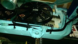
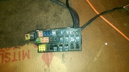
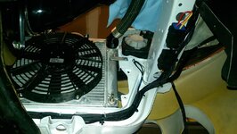
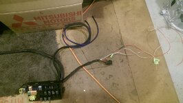
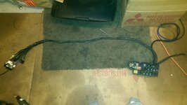
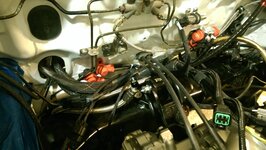
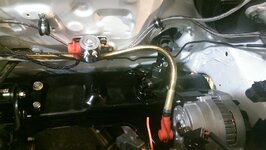
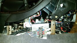
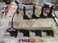
I am using the factory 2G DSM engine fuse/relay panel to send the signal for turn-on of 2x external SPAL fan relays.
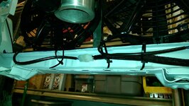
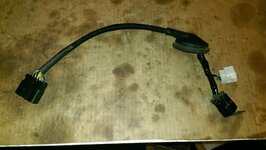
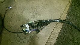
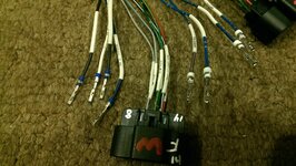
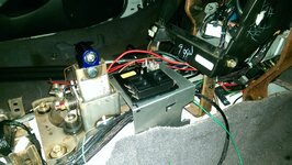
The setup is two SPAL fans each with their own relay; main 12V is straight from battery, chassis ground, and using the SPAL relays signal wires run to the combined Fan HI/LOW relays power wires. The factory fan HI/LOW relay GROUND wires (black and black/blue wires) are combined and grounded to the chassis. The factory fan HI/LOW relay POWER wires (white/black and white/blue wires) are combined and are wired to the SPAL signal wire. The factory wiring of the fan fuse is being retained and changed from a 30A fuse to a 50A fuse.
Essentially, I am using the 3x factory fan HI/LOW relays (and fuse wiring) to signal the combined SPAL relays to turn on in an ECU fan HI or LOW signal. The fans are only going to be 1 speed anyways.
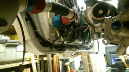
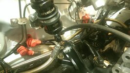
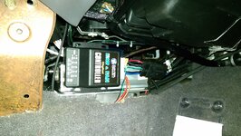
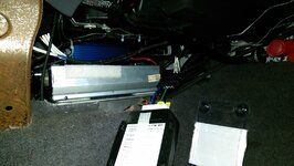
As well, I am using an electric water pump and pump controller (Davies Craig EWP115 8050 kit), so I will be using the ECU fan HI and LOW signal wires (Pin 20 and 21 on 2G ECU) cut and spliced to the electric pump controller instead. This way, the water pump controller will turn on/off the fans instead of the ECU. I have combined the green/orange and green/black wires at the fuse box to the pump controller fan signal wire.
I know I could have made it easier on the wiring side and deleted the fan LOW relay altogether in this circumstance considering that i am using the external pump controller, but I kept the wiring like this for reference if someone is still using the factory ECU to control LOW and HI signals from pin 20 and 21.
Just confirming that this would work properly. From looking at it, it should just fine but I wanted agreement from others.
I am doing something a bit unique, and likely overkill, but I need to confirm wiring signal.
I am using the factory 2G DSM engine fuse/relay panel to send the signal for turn-on of 2x external SPAL fan relays.
The setup is two SPAL fans each with their own relay; main 12V is straight from battery, chassis ground, and using the SPAL relays signal wires run to the combined Fan HI/LOW relays power wires. The factory fan HI/LOW relay GROUND wires (black and black/blue wires) are combined and grounded to the chassis. The factory fan HI/LOW relay POWER wires (white/black and white/blue wires) are combined and are wired to the SPAL signal wire. The factory wiring of the fan fuse is being retained and changed from a 30A fuse to a 50A fuse.
Essentially, I am using the 3x factory fan HI/LOW relays (and fuse wiring) to signal the combined SPAL relays to turn on in an ECU fan HI or LOW signal. The fans are only going to be 1 speed anyways.
As well, I am using an electric water pump and pump controller (Davies Craig EWP115 8050 kit), so I will be using the ECU fan HI and LOW signal wires (Pin 20 and 21 on 2G ECU) cut and spliced to the electric pump controller instead. This way, the water pump controller will turn on/off the fans instead of the ECU. I have combined the green/orange and green/black wires at the fuse box to the pump controller fan signal wire.
I know I could have made it easier on the wiring side and deleted the fan LOW relay altogether in this circumstance considering that i am using the external pump controller, but I kept the wiring like this for reference if someone is still using the factory ECU to control LOW and HI signals from pin 20 and 21.
Just confirming that this would work properly. From looking at it, it should just fine but I wanted agreement from others.
Last edited:


 !! I seriously wish I had the time and patience to do that with my 1G... Someday...
")