bpk1337
15+ Year Contributor
- 116
- 5
- Oct 28, 2008
-
Phoenix,
Arizona
But why..No. The ecu will get confused occasionally and not know what cylinder it's on.
Follow along with the video below to see how to install our site as a web app on your home screen.

Note: This feature currently requires accessing the site using the built-in Safari browser.

This site may earn a commission from merchant
affiliate links, including eBay, Amazon, and others.
This site may earn a commission from merchant affiliate links, including eBay, Amazon, and others.
But why..No. The ecu will get confused occasionally and not know what cylinder it's on.
I'd rather use the 1gCAS for now instead of having to reset the timing, it's a pain with the 2g mount on the 6bolt. Anyway here's what I'm thinking. Looking at RRE's drawing could I just wire it as follows?
1gCAS wire 1 to 2gCAS Plug 2
1gCAS wire 3 to 2gCAS Plug 1
1gCAS wire 4 to 2gCAS Plug 3
Seems all you need is Signal, + and - so I don't see why that wouldn't work. Just ignore the CPS wiring. I've been considering this but wanted some advice on the wiring first. Anybody see a problem with this wiring?
I could be reading them wrong, but according to that link you post from RRE it looks like the wave-forms would line up fine though? Where are you getting this information Bastard?It's because a 1g sensor doesn't output the right waveforms for a 2g. It works but it isn't right. If you spend the money on the kiggly crank trigger why wouldn't you do everything to make it as good as possible.
It's because a 1g sensor doesn't output the right waveforms for a 2g. It works but it isn't right. If you spend the money on the kiggly crank trigger why wouldn't you do everything to make it as good as possible.
Ugg. No. I understand this perfectly. How is swapping injector wires going to change the output of the 1G CAS? It's not. The signal might be inverted, but it's still not the same signal. You can look at the trace and see the pulse widths are not the same. That's what counts. The ecu looks for the cam signal to be high at a certain point. If it isn't it thinks something is wrong and gives the random misfire.
This isn't rocket science. Running a 1g cas on a 2g will cause the random misfire, because the 1g cam signal isn't the same. You can turn it off with link or what ever, but that still doesn't make it right.
Really? News to me. How do you explain the misfire issue going away when the MAS baro input is tweaked? ECMlink or RRE I don't remember, mentions this mod when using a 1g. How does the ECU check for mirfire, is it continuous or just a test. What does it look for? I don't recall reading about someone having misfire issues with 1g CAM and Kiggly crank. Or maybe the 2g ECU accounts for the big rubber band between the two stock sensors. Maybe two totally different misfire algorithms. And when the 1g cam and crank is used, there is no rubber band. Haven't seen that asked before but maybe that's just too simple and common knowledge. Certainly the "confused periodically" (when the sensor outputs are always consistently and exactly wrong) hypo is the correct. Because "confused periodically" can be proven by what exactly. How would one replicate the condition, on demand. How do people make a sh**load of power the wrong way, and this info not be plastered everywhere on tuners. Oh right, because it's not rocket science and everyone knows, like the sky is blue to a simpleton. See I can be annoying too.
I like you Nate so I'll go ahead and address this. I agree with him, that's why I "Like" it. I am of the opinion that one should use a 2G cam sensor with a Kiggly crank sensor. As we sorted through and found out on page 1, though, the 1G CAS is usable with the Kiggly sensor, no problem. You feel this is the best approach and that's fine. Matter of fact, you make a good point about the Kiggly sensor failing and being SOL with only a 2G CAS; I may have to reconsider. In any case, I think we can both agree that the 1G CAS by itself is insufficient more often than not and that gamble just isn't worth the hassle. I'll also say that, in my opinion, eliminating the random misfire check in Link or the potentiometer added to the barometric pressure sensor wire are masking the problem, not solving the issue that has the 1G CAS at the root.Really. That post warranted a like. Faaaaceeeboook.
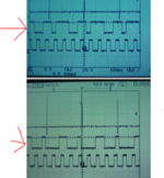
This is correct. Camshaft position sensor output wave patterns are pretty much the same for all years aside from the '95-'96 being inverted and having a slightly longer duration than (at least) the '97+. This is from the '97 FSM and just reiterates what is already listed in the Magnus article.If you look Here: http://www.roadraceengineering.com/1gcasin2g.htm at the 3rd bullet under "The Bad" RRE states the following:So, from that logic it would seem like we would have no problems with the crank signal if we are to use it with the Kiggly unit. The only thing we would need to worry about is to make sure that the cam signal is in time. Anyone feel free to correct me if I am wrong.
- Reported problems range from none, to annoying, so be aware. At the time of this writing the most common glitch is an increase in CEL's. The most likely CEL to occur is "Random Misfire" Possible problem sources for phantom misfires are intermittent electrical connections and/or noise in an unshielded wiring harness, harmonic vibrations in the timing belt system, or a bad CAS. OBD-II 2G ECU's were designed to detect misfires from a sensor reading directly from the crank. A simulated crank signal from the CAS may not be accurate enough for some ECU's.
Kevin,Our crank trigger sensor will work fine with either a 1g CAS or a late 2g CAS on a 1g or late 2g ECU. The 95-96 ECU needs the changes as-described in the RRE writeup if you are running a late 2g or 1g CAS. Alternatively, you can fix the invert CAS issue with the invert CAS option in ECMLink (if you have it). There isn't really an advantage to the 1g CAS vs the late 2g CAS. The latter looks a little better, but both are totally valid signals.
The misfire code should not be a problem with our sensor. As stated previously, the problem with the 1g CAS and misfire code on a 2g is due to its location and all the torsional 'activity' the cam sees from opening the valves and timing belt loads / whip.
Oh, we'll have the updated V2 crank trigger available as a 2-tooth soon, just waiting on some final feedback of parts out in testing.
Thanks,
Kevin
Our crank trigger sensor will work fine with either a 1g CAS or a late 2g CAS on a 1g or late 2g ECU. The 95-96 ECU needs the changes as-described in the RRE writeup if you are running a late 2g or 1g CAS. Alternatively, you can fix the invert CAS issue with the invert CAS option in ECMLink (if you have it). There isn't really an advantage to the 1g CAS vs the late 2g CAS. The latter looks a little better, but both are totally valid signals.
How is the crank immune to this? ATI has quite a bit of published images showing as much as 10* peak-peak crank twist at the damper. Surely that would be enough to double trigger it? What is the max frequency of the sensor you are using?The misfire code should not be a problem with our sensor. As stated previously, the problem with the 1g CAS and misfire code on a 2g is due to its location and all the torsional 'activity' the cam sees from opening the valves and timing belt loads / whip.
Kevin,
Thanks for the response. When using the 1g cas with your sensor, does one need to set base timing with a timing light before installing the kiggly unit? Or can we just wire it up and go?
I didn't care for bastards accusation that someone using 1g is doing it wrong and isn't as good as possible, like they are fully educated on their decision to be a cheapskate. Based on waveform pictures.
It appears to me he isn't aware that the 1g sensor is not the problem for misfire codes. It is the placement of the sensor, specifically the crank sensor. OBD2 uses the crank signal for its misfire monitor. DIRECTLY FROM THE CRANK. When using the 1g, it is not a true crank sensor. That is the WHOLE simple deal with the misfire BS. Like, can we move along now. And then the rocket science card is pulled out. Yet nothing useful from alllllll his posts has come to light. And a mod liked his post. Just got me a little annoyed.
I didn't care for bastards accusation that someone using 1g is doing it wrong and isn't as good as possible, like they are fully educated on their decision to be a cheapskate. Based on waveform pictures.
I don't care for you putting words in my mouth. I said if you can use the right sensor use it. If your running the kiggly crank trigger you have no reason to not use the right sensor.
The oscilloscope doesn't lie, by the way.