The Top DSM Community on the Web

For 1990-1999 Mitsubishi Eclipse, Eagle Talon, Plymouth Laser, and Galant VR-4 Owners. Log in to remove most ads.

Please Support RTM Racing
Please Support ExtremePSI

Speed Density IAT sensor install, pre-or-post throttlebody

This site may earn a commission from merchant
affiliate links, including eBay, Amazon, and others.

This site may earn a commission from merchant affiliate links, including eBay, Amazon, and others.

performance

10+ Year Contributor
142
3
Jun 28, 2011
Chattanooga, Tennessee
I have been doing some research on converting to speed density. Honestly, MAP sensors are what I am used to seeing on vehicles that I have owned. My question/observation is that most-to-all vehicles that I have worked on or owned has their IAT sensor located on the manifold itself, mostly between cylinder 2-3. This reference seems to be an accurate location to read temperature that has accumulated from the manifold. If there is a rise in temp, post throttle-body, wouldn't one want to account for the change in the temperature for the tune. Can the manifolds heat affect the sensor itself? I can see that pulling out an UICP out is a lot easier than an intake manifold. I figure if many of the preeminent automobile manufacturer's are engineering engines in this manner it has to be the proper way. I do not have an engineering degree, nor am I the sharpest tool in the shed. I firmly believe that there is only 1 way to do things.... the right way. I'm just not sure what is "right." Chime in, Let me know what you guys think.
 
Honestly I haven't seen that many people run it on the manifold. I'm not sure if your seeing the MAP sensor there and confusing it or actually know people or have seen people run the IAT sensor there, but my SD set up was like this; I had my GM IAT 4-6" from the TB on the UICP and the Omni Power 4 bar MAP sesnor directly on the manifold mitsu style sensor. My new set up is a little different because of the SMIM, I have a gm style omni power 4 bar map sensor and would be making a bracket to get it closest to the manifold as possible, but the IAT sensor will still be on the UICP. Ill do more research and try to find out more about the way your mentioning in the beginning of your post. Hope this helps.

Anthony B
 
I wouldn't recommend because of the heat from the head transfers to the intake manifold might give you an inaccurate reading. The intake manifold gets really hot while the upper innercooler pipe stays a lot cooler, I would put right before the throttle body.That's just my 2 cents. Also newer cars use plastic intake manifolds that don't get as hot because they can dissapate heat better.
 
Just for comparison, a SRT4 has it stock about 5-6" in front of the TB on the UICP.
 
Just want to add that the IAT sensor tap for SD I have on my Evo is on the Upper Intercooler Pipe about 3 inches away from the Throttle Body on the pipe.
 
There has been some compelling evidence to place the IAT sensor 3-6 inches from the TB. I only based my assumption on my old "filthy" habit of building Hondas. I have considered the heatsoak issue. I thought that I needed to have an accurate/truer reading for the hotter air due to the Intake raising the IAT. I guess that's what an EGT probe and wideband is for.
 
If you don't have a functioning EGR valve, then changes in air temperature before/after the throttle body are negligible. The biggest issue with the IAT being post TB (apart from what you mentioned) is that airflow isn't uniform through the manifold. An IAT sensor located at the end of the plenum (opposite the TB) would typically see much less airflow than a sensor located right at the runners.

I would consider optimal placement to be:

• 3-6" away from the TB, or at least after the BOV.
• At or near the apex of the UICP elbow.
• In the lower 180° portion of the pipe, depending on how much moisture will accumulate in the intake.

Here's my IAT placement. I've found the readings to be very accurate, and I've seen intake temps from below freezing to over 100°. Sometimes just days apart. LOL
You must be logged in to view this image or video.


You must be logged in to view this image or video.
 
Couldn't find a more recent picture:
You must be logged in to view this image or video.


I actually have two spots setup to take IATs, one pre-intercooler and the other above. "X" mark in the foreground, upstream of the meth nozzle not the mark on the TB
 
I have been doing some research on converting to speed density. Honestly, MAP sensors are what I am used to seeing on vehicles that I have owned. My question/observation is that most-to-all vehicles that I have worked on or owned has their IAT sensor located on the manifold itself, mostly between cylinder 2-3. This reference seems to be an accurate location to read temperature that has accumulated from the manifold. If there is a rise in temp, post throttle-body, wouldn't one want to account for the change in the temperature for the tune. Can the manifolds heat affect the sensor itself? I can see that pulling out an UICP out is a lot easier than an intake manifold. I figure if many of the preeminent automobile manufacturer's are engineering engines in this manner it has to be the proper way. I do not have an engineering degree, nor am I the sharpest tool in the shed. I firmly believe that there is only 1 way to do things.... the right way. I'm just not sure what is "right." Chime in, Let me know what you guys think.

you can run the iat anywhere in the intake ducting pre or post throttle body. i work on a lot of different cars and have seen them before the throttle body and after the throttle body. all the iat does is to help determine the correct amount of fuel to add to the air. in speed density systems the map sensor tells the computer pressure and vacuum readings whille the iat tells how hot the intake air is (and or how dense the air is as well) to determine the amount of fuel to the air. when the iat reads colder temperatures the air is usually denser and with a higher vacuum reading (above 14 inches of vacuum) input into the computer it will then turn around and add a pre-determined amount of fuel that has been programmed into the fuel map table for those input readings from the iat and map sensor. speed densisty is basically a trial and error operating system; were as a maf system is exact without the guess work.

though the best spot for FI is usually just before the throttle body for best iat readings or after the throttle body.
 
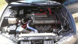
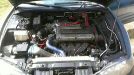
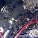
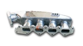
I am working on installing my IAT for speed density. I have an unusual set up and do not have a location to place the IAT 6 inches from the throttle body and away from the BOV. Would I be better off installing it into the SHIM? I could place it in the post trottle body neck on the shim or in the plenum of the shim as well. What are your thoughts?

Here are some additional pics. The manifold is the same design as the one labeled maxspeeding but construction is slightly different as mine is made from two cast pieces where the maxspeeding appears to be 3 pieces or the plenum is made of sheet metal requiring extra welds on the tb neck.
 

Attachments

  • 002.jpg
    002.jpg
    50.6 KB · Views: 723
  • 144.jpg
    144.jpg
    42.2 KB · Views: 802
  • 095.jpg
    095.jpg
    22.1 KB · Views: 680
  • Eclipse Inake Manifold.jpg
    Eclipse Inake Manifold.jpg
    23.6 KB · Views: 1,017
Last edited:
Support Vendors who Support the DSM Community
Boosted Fabrication ECM Tuning ExtremePSI Fuel Injector Clinic Innovation Products Jacks Transmissions JNZ Tuning Kiggly Racing Morrison Fabrications MyMitsubishiStore.com RixRacing RockAuto RTM Racing STM Tuned

Latest posts

Build Thread Updates

Vendor Updates

Latest Classifieds

Back
Top