The Top DSM Community on the Web

For 1990-1999 Mitsubishi Eclipse, Eagle Talon, Plymouth Laser, and Galant VR-4 Owners. Log in to remove most ads.

Please Support ExtremePSI

diagnostic help

This site may earn a commission from merchant
affiliate links, including eBay, Amazon, and others.

This site may earn a commission from merchant affiliate links, including eBay, Amazon, and others.

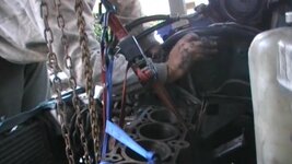
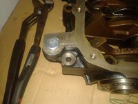
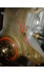
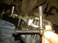
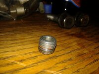
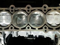
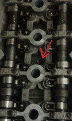
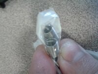
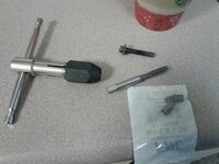
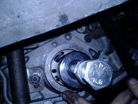
I had a real problem with a stripped connecting rod bolt. fyi drilling it would have been better. I hack sawed the top off but i couldnt get a good angle and ended up cutting into the connecting rod. I was planning on upgrading the connecting rods anyway but if i wanted to keep them i think i could have drilled it and salvaged the connecting rod. once the top of the bolt was off the rest of the threads were fine and the bolt came out easily. I thought the threads were crossed from the spun bearing... because I used an extractor tool and could not budge the bolt.

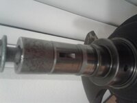
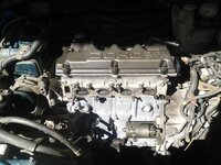
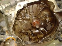
I am working my way to the crank and I am going to take that and the block to the machine shop for cleaning and repair. With upgraded connecting rods everything else will be cleaned and put back together.

I am thinking of a strut tower bar that will allow me to lower the engine from some kind of fabric strap system. I have been into rock climbing and rope systems for a long time and I am experienced in rigging these kind of systems. well not these kind of systems however ones that I would trust to hold in a fall. rock climbing straps will be able to hold the 200ish lbs of the block. I just will only use the engine hoist once and funds are tight so this is the plan.
 
Look into renting an engine hoist, you don't need to buy it, but it will be far safer and will make the job far easier if you have something purpose built. I've also seen people build A-Frames out of steel pipe and hang a come-along from them. That's sorta like what they've got at pick-n-pull.
 
I almost had it but i backed out before i got the engine mount off. So the plan is to use a chain hoist and tow straps. I have removed everything except the block and crank and transmission. I removed four bolts from the transmission to the engine. I tried to remove the passengar mounting brackets to create room for the engine to slide out of the transmission. I want everything to retain it good condition so i am posting for help here. Maybe i will make a new thread for this help only. I like this because i want to keep the transmission in the engine bay and not have to hassle with taking out the axles and fluid and other connections.

Do I have to remove the rear mount of the transmission to the frame?

That seems to be my biggest problem holding it in but the transmission will hit the ground or just fall as it is separated from the engine... I need to support the transmission for after the separation somehow with wood and then remount the transmission.

Thank you.
Also dsmmute was helpful with his youtube post of his transmission removal video was helpful with my separation.

Theres a fifth bolt underneath that was at the end of his video. I remember now but am still going to try to think of a way to be gentle withthe trans mission separation.

I appreciate the engine hoist rental advice however i found this chain hoist. The strut tower bar has little room and may only be helpful in lowering the entire engine and transmission.

Ok tried again. In the picture i am unable to get the last bolt with the crescent wrench. I know there is one more bolton the bottom but theres less than an inch clearance as it is... I am going to figure out a way to apply more torque tomy crescent wrench because thats all i can get in there...

When i get the passengar mounting bracket will there be enough room to separate engine from transmission?

Conclusion I did not need to take the motor mount off though it may have been easier. I highly rwcommend taking the lower front bolt out last because it had the tapered tip or at least thats the one I put in there temporarily while i took out the bottom most bolt. The brake cylinder had to come off to get the plate off. Careful of coolant drips which is not oil but stains. Once the bolts were removed and i had it supported by my chain hoist I was able to lift up on the transmission because the weight of the transmission was keeping them together. The rear transmission mount stayed on the entire time. Rotated engine mount forward as i lifted engine out and rolled talon back and dropped it onto my moving dolly. Ghetto a little but I am in debt right now and want to do this myself and I like this car. I am learning and maybe Ill build it up but I certainly have a much better idea of the parts.
 

Attachments

  • 20130806-072645.jpg
    20130806-072645.jpg
    31.5 KB · Views: 95
Last edited:
I found the bedplate to be on there good and in order to prevent damage I used a long bolt with a nut on it to tighten down through a corner part as pictured. This area is strong and i was able to separate it with no scratches or damage. I used some other stuff too which got scratched instead of the engine. The oil pump required a light hammer touch. I have not gotten the crank pulley off yet but i will today. I expect to be posting again pictures of a cleaner working engine bay. I cant afford to build the engine quite yet. I will get some more use out of it as nt.
 

Attachments

  • 20130811_103006.jpg
    20130811_103006.jpg
    41.9 KB · Views: 108
I will detail the crankshaft pulley and the crankshaft pin. There is a video on how to make a washer adapter to use the claw puller device. I ended up using a different puller kit which uses m6-1.0 bolts that fit it into the crank pulley. I ended up bending those bolts but the pulley came off smoothly. Try to find greater than two inch bolts and i used nuts as washers cause theyre stronger. The bolts fit though the puller without washers. Pictured is the crank shaft pin hole. This was simple but in there good. I used vice grips on it and hit the vice grips and it came out with no scratches other than my previous attempts. Plyers were not strong enough once i figures out it was a removable pin. Obviously store it securely while crank is machined.
 

Attachments

  • 20130812_223601.jpg
    20130812_223601.jpg
    24.5 KB · Views: 86
Last edited:
So I have my block and crank back from the machine shop where they were cleaned and polished and the crank was ground and I am using over sized bearings on both main bearings and connecting rod bearings to compensate for my crank being ground down. The block surface was polished and the cylinders were honed. I had planned on upgrading the connecting rods but I am just getting back to stock for now. In the process of putting it back together I would like to make a few notes for non mechanics. I had to hammer in "freeze plugs" which are 50 cents and the bedplate girdle requires a gasket called anaerobic sealant which is basically a thin gasket. This requires an activator.


My question which I will attempt to answer but could not find confirmation of my suspicions. This hole as marked in my picture is resolved to have this plug. Another one is on the other side.

which cylinder gets the flat piston?
 

Attachments

  • Sketch301222754.jpg
    Sketch301222754.jpg
    26.6 KB · Views: 105
Last edited:
I am following the pdf available through this site called 420a overhaul and this is good for most of the process. The head bolt torque pattern is in there which includes 46 lbft for the long bolts and 20 lbft for the four shorter bolts. I did over torque one of the cam caps on the head after bolting it down. by the way the head cannot be bolted down with the cams on. The smaller cam caps are only nine lbft and I have even read that using lock tight and just getting them tight is enough. 10lbft is pretty easy. The soft aluminum is easy to strip and this is going to be a huge problem to re-thread. Well not a huge problem it can be done a few different ways via heilicoils or in my case thread locker however I may use heilicoil when I put a turbo on it. I did not find the flywheel plate torque specs in the pdf which are 100lbft although I did closer to 75lbft because I also used thread locker and the bolts would not budge any more and they seem sufficiently tight to me. The clutch to fly wheel torque was also only on here as 55 lb ft . One of the cams was hard to rotate with the greater torque that I applied.

The head installed with all valves closed but as i was rotating the crank and pistons to install the clutch it wiuld not make more than one complete revolution. I could rotate it almost bqck to the same spot and it seems to be catching on something. Could this be caused by the orientation of the pistons? I failed to mark which cylinder each piston came from and there is also a dimple that is not always on the same side. The tiny hemisphere is on one side and three are the same but that could not cause this. I need to rule this out before i try to start the engine....

After removing the head and pulling the one the had the indicator on the clutch side and the rest are on the oil pump side.
This could have caused some significant damage so be sure to line the pistons up right. It will also be easier to install the block first into the engine bay and then attach the head, it will be lighter and smaller this way.

There is one screw plug thing i can find where it goes. Its a bigger diameter screw and half inch long with a hex hole in the back to drive it in. It was returned to me with block from.machine shop. It is some kind of plug i cant find where it goes?
 
Last edited:
Alternator
pictures
I could not find this alternator bracket and I could not find this image anywhere on the internet either.

My block went into the car today. I reversed my removal with a chain hoist and angling it into position and bolted to transmission. This required a jack under the transmission after bolting the passenger mount. I put it under the transmission mount.

Can anyone tell me where the socket bolt goes because it was rerurned to me from the shop which cleaned my block. I did not take it out.im not even sure its mine or goes in my engine?
 

Attachments

  • 20131012_111650.jpg
    20131012_111650.jpg
    46.3 KB · Views: 97
  • 20131012_162658.jpg
    20131012_162658.jpg
    44.8 KB · Views: 92
  • 20131012_111517.jpg
    20131012_111517.jpg
    40.5 KB · Views: 90
  • 20131013_131552.jpg
    20131013_131552.jpg
    61.4 KB · Views: 94
  • 20131013_122732.jpg
    20131013_122732.jpg
    59.7 KB · Views: 105
Last edited:
That is an oil passage plug, probably in the bell housing side of the block. Make sure that they are all in place. A good machine shop will remove them and clean the oil passages.
 
Ok so this picture is my best guess at this oil plug. The socket bolt i have is smaller than this one in the head. The hole I have identified in previous posts on clutch side of block is coolant plug to the best of my knowledge. I have placed a small freeze plug in a hole on the clutch side which could have fit this but I am too far along now to check without pulling the block again. I am confident that is a coolant plug in the clutch side of the block. Unless there is another oil plug that I cannot find I am going to seal it up and tighten it down tonight.
Thank you for the reply.

edit:
The coolant leaked out the back of the block where the socket bolt seems to have the right size and would make sense in this spot. I threw the socket bolt out when cleaning up and thought is was not used. I pulled one from the picknpull but it was a normal bolt and not a socket bolt but I think its the same size and makes sense.
 

Attachments

  • Sketch15211550.jpg
    Sketch15211550.jpg
    28.6 KB · Views: 99
Last edited:
Locktight does not seem reliable enough for a cam cap. It is the smaller bolt that i mistakenly tightened to 20 lbft instead of eight lbft. Its only 8 lbft and i was thinking locktight and the larger 20 lbft bolts might have held temporarily. Researching solutions ive decided to use a thread replacement coil product. This is probably a machine shop project however my head is bolted down and torqued again and i am going to attempt to tap the larger threads for the thred coil. The aluminium is soft and i just need to keep it perfectly vertical or perpindicular to block cause its mounted kind of at an angle in the car....
 
I have just finished my new threads on the head. I left the cam caps in place as the four I stripped were all on the same side. The tap bit fit inside the cap hole. Pictured are parts used by me. It recommended a drill bit size however my threads were well stripped so i did no find it necessary in addition to the aluminum being relatively soft. It did not give a problem. I studied this process and it makes sense to be firm to carve out the outer threads but just enough. It would be possible to strip the threads your making. I found the stripped threads provided just enough material to guide the tap bit. The tap bit will carve out and the coil of new threads screwed in. This was a good spot for a beginner because these are at eight pounds of torque so they do ot require significant torque. I did select the larger thread replacement of the two options because I expected them to fit. This is not intended to replace all the threads just provide enough to be sufficient. You can stack replacement thread coils if necessary but thrre will always be part at the end which will not be tapped by the bit becauee of how it works. So carve some threads and back out and clean the tap and realign carefully and thread it carefully and carve out more. Material will collect at the bottom so it needs to be cleaned out half way. Clean again before installing the coils. I used q-tips which collected the shavings well. Careful not to let any shavings fall into oily areas for obvious reasons. These metal shavings could get into rotating surfaces and cause damage. I fit the bolts to the bottom before i put the coils in. There is a thing that allows the coils to be screwed into the larger threads which gets removed. I have not removed it yet but my new threads hold great and there is not resistance screwing the bolt in.

Insert screwing joke here.
 

Attachments

  • 20131111_110048.jpg
    20131111_110048.jpg
    34.5 KB · Views: 97
  • 20131111_101844.jpg
    20131111_101844.jpg
    53.4 KB · Views: 79
Last edited:
Today I have the cam caps bolts torqued to 8 lbs and specification. It feels like its stopping and the coils coild hold more and will hold the cams down. I did have to hack about a quarter inch off the bolts for the holes i fixed with helicoil types. The tap doesnt cut at the tip. It may be a better solution to use the solid inserte thohght i expect these will hold fine. I put the head cover on as well. I just have some sensors and ill need a few more things.
 
I have read on here that a way to install the crank pulley is to obtain a longer bolt of the same thread pattern to allow for all threads to bear the pressure of installation of crank pulley by tightening down a nut. This avoids damage to female threads of crank and also breaking off bolt inside crank. A separate bolt could prevent damage on removal also.

I have a problem right now of the bolt that I purchased not being exact fit. I have researched the thread patter to be m12x1.75 the length is undetermined. I found a replacement on ebay that looks good and I have determined that i purchased a fine thread and the bolt is coarse thread. I have ordered a coarse thread bolt and I will use that one to install the crank pulley if it is correct. all are the same thread pattern. the one needed is a "tap" bolt which has threads the entire length.
...
I have pressed on the crank pulley with the bolt I purchased of 8.8 hardness and m12 x 1.75. The problem was that there had built up dirt or something on the inside of the crank. I did not expect it to be dirty coming back from the machine shop and I remembered it being a hand tight fit and easy fit. The second problem that I had was that the little pin on the crank came off as it was being pressed on. I did my best to line it up. I was pretty close but I will have to pull the pulley again before putting significant torque on this or risk the timing being off.

Significant note: I installed the crank pulley backwards. The lip should be out. I did not press it all the way down and I am going to use the claw puller to hopefully correct my mistake and also not risk leaving it on without the pin holding it in placed and keeping it from spinning and throwing off the timing. The pin issue was why I did not press it on all the way. I know it on there tight and may not spin but the pin will assure that all my hard work does not result in a blown engine.
 
Last edited:
I am just about ready to put fluid in and start it up as soon as I track down this last wire harness connection. Pressing on the pulleys onto the crank has been the most challenging but I have just gotten the timing alignment completed. The water pump has a rounded front side to it which is how I got the timing belt on. I could not use torque the tensioner because I'm working inside the engine bay. It is important to note that the timing needs to result in being aligned however the belt goes on. I have taken a picture from when I am pressing the crank pulley on and pointing to the arrow on the pulley which is aligned to the top arrow which puts all the pistons at the top. While that is aligned the cam gears need to have their marks meeting in the middle as close as they can be to each other. This also puts one up and one down of the pins on the cam gears which can be seen without the bolts into the cam gears. This is critical.

There is a thread asking about the wiring harness which I was interested in but it is incomplete because you pretty much figure it out as you start plugging in sensors. Obviously keep anything clear or rotating parts and zip ties help that. You should be able to start from memory and work your way through or just start fitting sensors to wires. rarely will two fit the same thing, I'm not completely done yet with the wiring.

In hind site the head may have been able to be on the block when installed in the car and it would have been easier to do timing and torque down all pulleys and press on crank pulleys in a shop on a stand. Ideally that would have been better but its possible to have the head off as I did, if necessary. The timing belt needs to pass through the engine mount which is a long process to do if already installed. This is another reason to do the timing belt early if not prior to putting the engine into the vehicle.

There is a clearance issue which involves the crank shaft fitting into the transmission and the opposite firewall. I found it easier with only the block to maneuver into place however it would be worth it to have the timing done prior to installation. I don't think doing the timing prior to installation would have effected clearance only minor additional weight of head.

I regret not putting grease on the throwout bearing prior to connecting transmission to engine. I hope it does not squeak.

Just be careful not to try to hang the engine from the aluminum head for sure.
I used two ratcheting straps without the oil pan on the bottom around the entire block.

You can tell from the picture that I have a longer bolt than the stock crank bolt and a nut. In addition to a large socket that is for a 1/4" driver so the bolt fits through. I tighten the nut down while holding the end of the bolt. The pulley will go just about flush with the oil pump.

Edit: after going to picknpull theres an engine hanger point on the head. This bracket was removed from my engine. Do timing belt prior to harmonic balancer. Im starting with synthetic because not complete rebuild and its clean now. I imagine regular oil would help break in but switching from synthetic to regular might change viscosity... although yhey make blends.. im pitting synthetic to start.
 

Attachments

  • 20140104_122845.jpg
    20140104_122845.jpg
    49.6 KB · Views: 95
Last edited:
upon filling fluids the water pump never received a gasket. I applied a permatex anabolic gasket maker for a temporary solution so that I can pass smog and have legit registration while I make more permanent improvements. This was required for the bed plate to block surface.

I had already pulled the nail from the timing belt tensioner so that will be extra unnecessary work had I not done that... because my timing belt came off via cam gear removal. I ended up taking off the cam gear to remove the timing belt because I could not get the pin back in the tensioner and I could not get the tensioner off and the bolts on the water pump are very small and I did not want to risk damaging them by removing the water pump under tension. So the cam gear loosened the timing belt.

The water pump can be resealed in three hours by a novice. getting the timing belt back on is another matter. The water pump is still got a bolt through the engine mount and into the block so additional steps are required to remove the engine mount bracket. I just took off the power steering and put a jack under the engine with a piece of wood and removed the engine mount as far as it would and the water pump was accessible with a 10 mm wrench and socket for four of the six bolts. An extra long 17mm socket works good for the engine mount from the bracket. that separation may not have been necessary however after removing the engine mount so many times this makes the installation much easier and probably gives a little more play to get at the water pump...
 
This plug was not obvious to me and I posted this as a question earlier in the thread where I asked what the plug was.
My coolant drained out the back of the block near the freeze plug. My water pump did not seal properly either. The water pump is a mistake however this plug was not obvious to me. There are several other threaded holes that serve no apparent purpose. I don't expect they serve no purpose but they have been removed by previous owners. Or they are engine hangers or manufacturing functions.

Other not obvious parts that came off during block cleaning and machining are a ground from the intake to firewall and a ground with a diode by the starter. The diode is going to allow for only this circuit to ground to the system and no other ground current will pass through this circuit. The diode is a one way ground attaching to the larger grounded system.
:cool:
 
Last edited:
My hiccup has been the water pump which I failed to seal properly in the first place. The problem really is that I had to remove the timing belt after the pin had been removed from the hydrolic tensioner. I had gotten the belt on OK with out the pin removed. Once I sealed the water pump and put water in the system I had to remove the tensioner to put the timing belt on but I could not take it all the way off because the harmonic balancer had already been pressed on which was not easy. I did not want to take the harmonic balancer off so I flattened a damaged bearing and used it to pry the tensioner into place as I tightened the bolts to the tensioner.

I did not want to remove the harmonic balancer because The engine had to be lowered on the passenger side and a special tool has to be borrowed from the auto parts store. I am not sure the coolant system will move that much without springing a leak either.

This was not the best practice and I recommend avoiding this situation in the first place which I why I am posting this and not for this to be intentionally used unless out of necessity.

I am going to rotate the engine a few times prior to starting it to insure that the timing is right. I will start it this weekend.
 
Last edited:
So i turned it over for the first time with no ignition.

Probably good because the fuel line connection was leaking and oil was coming out from somewhere. I jacked it up and found no obvious origin. My best guess is the oil pan which had one bolt with damaged threads to the block. That is my best guess at this time. The oil was leaking out from the back near the transmission where my one bolt was stripped on the oil pan. I did not think it got very much pressure. I am happy that it wasn't the oil pump and the internals rotated correctly. I was extremely nervous about more significant issues.

Two oil pan bolts were not tight enough on the transmission side which made me suspect the main seal. Fortunately I have not done the transmission. It is still not starting. just a clicking from the starter which I thought was a low battery which I put on the charger but still the same clicking.

Upon testing of the starter I purchased a new negative battery terminal because my gold plated one was not tight. she started right up. I shut it right off to give me all day tomorrow to make sure it runs purrfect.
 
Last edited:
Today my starting issue turned out to be the starter which decided to also not work but that's an easy fix. It starts up consistently however I believe my timing is off by a notch because it is running rough. My gauges are not working although I believe that may not be entirely new thing. I have already swapped out the gauge cluster. I think my sensors are not all giving me tach. readings. I know where the transmission sensor but that is certainly not the tach..

ok well video loading problems but I am working on perfecting the timing now.

Which sensor sends tach readings?

I am happy that I can use my hid bulbs as high beams only and regular lights for non-glare reasons.
 

Attachments

  • PIC_0348.JPG
    PIC_0348.JPG
    17.8 KB · Views: 92
  • PIC_0345.JPG
    PIC_0345.JPG
    16.1 KB · Views: 117
So no leaks until it ran and then what appears to be the rear main seal leaked, which I reused. I am just trying to get it running at this point... I believe there is an exhaust leak as well. there is a check engine light which should have been my first thing to check. It is running so the sensors must be working...
almost there...

I replaced the started but I just had weak battery terminal connections which was my initial starting issue.
 
So two leaks are in the crank position sensor and more mysterious and challenging is the rear crank seal between engine and clutch/transmission. Ive lifted the engine a few times and for two reasons ive put it back cause i could loosen the clutch xause the engi.e spins and there was no oil on cluth which confused me. I guess 1000 rpm spins it off fast.
 

Attachments

  • 20140413_170922.jpg
    20140413_170922.jpg
    60.1 KB · Views: 85
Today but it seemed odd to me at the time with no oil on the clutch. Upon reading more about it this is consistent with the rear crank seal. No previous problem prior to rebuild and not daily driver.
A picture of this orange seal earlier in this thread.
 
Support Vendors who Support the DSM Community
Boosted Fabrication ECM Tuning ExtremePSI Fuel Injector Clinic Innovation Products Jacks Transmissions JNZ Tuning Kiggly Racing Morrison Fabrications MyMitsubishiStore.com RixRacing RockAuto RTM Racing STM Tuned

Latest posts

Build Thread Updates

Vendor Updates

Latest Classifieds

Back
Top