PXHero
10+ Year Contributor
- 166
- 9
- Aug 19, 2008
-
Columbus,
Ohio
Quite some time back, I started a rebuild project on my 99 GSX. It's moving along sloooooooooooooooooowly. However, I finally have enough done on my gauge cluster to write up a bit of a tutorial.
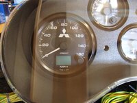
First things first, remove and disassemble your cluster. If this is difficult or heart breaking for you to do, you won't like what's coming up, turn back now.")
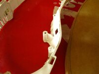
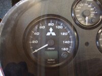
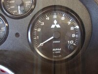
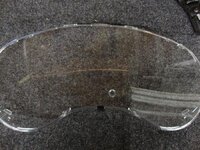
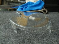
Break it down to the parts shown above. Since I don't know the proper names for these items, I'll just call them (in order) glass, box, and trim. The box is (at least for the sake of this tutorial) facing you, with the bottom facing the bottom of the image.
I trashed all the extra pieces of my old cluster since I wouldn't be using them in my new one. I did make a note of my milage, just on the off chance I can input it into my new speedometer's odometer.
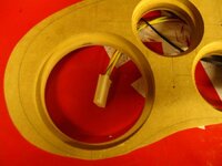
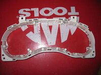
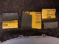
Next I ripped out the excess plastic trim around the old gauges and lights. Be careful to leave a bit of plastic trim around the edges of the old cluster. It's much cheaper to buy sand paper and get it closer to the vertical walls of the trim than it is to buy another cluster.
After I got the majority of the trim out, I went back with a drum sander and got the rest so it was flush with the walls. I also got a bit of the wall with the sander, but that's ok for my application because I will be using a texture coating on all the surfaces for an "OEM" look.
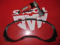
For the next step, I begged my boss to use the shop's scroll saw. If your boss is as forgiving as mine, he won't mind if you break a few blades. (I broke 3... Not bad for my first time using a scroll saw though... Anyway, back to the tutorial)
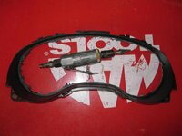
Cut out as much of the plastic back as you can while still retaining the supports (detailed in the second photo above). These will be holding your new gauge plate in place by pressure so you won't need glue or screws. Now that the back of the box is open, you'll notice that it's VERY flexible. Take care not to flex it too far, it will break.
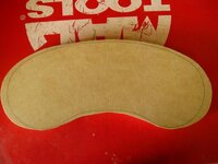
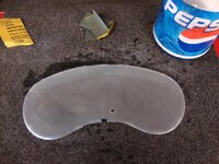
Because I opted to flush my gauges into the cluster, I used 3/4" MDF (Medium Density Fiberboard) for my new gauge plate. After that last step, I got sidetracked and forgot to take pictures of shaping the MDF to fit the cluster, but maybe I can get enough words out here to give you the idea.
I cut down a piece of MDF a little larger than the trim piece. Then I did a lot of sanding on the belt sander to get it the approximate shape of the trim. Since the 2G cluster has a slight angle at the bottom of the box, I needed to bevel the bottom edge toward the back of the plate. This took a little guess work, a lot of luck, and a lot of test fitting. And honestly, a second piece of MDF and a "do over." Once the second piece of MDF was close enough for who it's for (me) I proceeded to further modify the box.
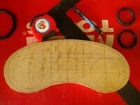
The "finished" plate, complete with trim tracing.
I did this using a very rough sanding disk chucked into my drill and a little downward pressure. Since the plate I used was 3/4" thick, I measured flush from the front side of the box down 3/4" on each support. I made a nice 3/4" template for this using scrap from my gauge plates. I drilled a hole into the scrap that was about the same diameter as the support posts, and then cut the piece roughly in half, bisecting the hole. Then I placed the box face side down onto a table, placed the template's groove onto each support, and made a mark. Easy as that! Then a little grinding, a little test fitting, a little grinding, a little test fitting, etc. Until the plate fit flush with the front face of the box.
Next I plotted out where I wanted the gauges. This took a lot of time, and measuring, marking, erasing, remeasuring, remarking, etc. Finally, I ended up with this!
If I wanted to go through the headache of reforming another gauge plate, I would only do 4 gauges in the cluster. It's much more forgiving because it allows for more space between the gauges, and being 1/32" off in your measurements doesn't show as clearly in the final product.
After I got everything plotted, now it was time to beg the boss to use the drill press. After permission was granted, I chose a hole saw that was as close to the diameter of the smaller gauges as possible. (Your forgiveness is required here as well, since I once again got sidetracked and didn't take pictures of the process. Those pesky customers, always wanting to buy stuff...
  ) I recommend using a tiny drill bit to get a pilot hole started for the center of each gauge location, and then stepping it up to something about 1/2 the size of whatever bit is in your hole saw. I clamped the gauge plate to the press, and began cutting holes. Once the small gauge holes were cut, I repeated the process on the larger holes, using the appropriate size hole saw of course. I highly recommend the use of a drill press for this portion, because if you don't get the holes exactly parallel to the plate, then your gauges won't sit right in the cluster. Also, don't be surprised if you can't find a hole saw the exact size of your gauges. My larger gauges slipped easily into place, but I had to sand out the holes for the smaller gauges a bit in order to get them to fit right.
After all the holes were cut, it was time to create the counter sink to flush the gauges. Using a router, a flush bit, and a good assortment of bearings, I carefully routed the counter sink for each gauge. The key here is to find a large enough flush cutting bit, and a bearing that will make up for the leftover space between the chassis of the gauge and the overall diameter of the gauge. (This process would have been much easier had I not purchased surface mountable gauges. If you have straight body gauges, ex. 52mm face with a 52mm chassis, you won't need the router, but you will have to glue the gauges in place in the later stages of the build) Using more of the scrap from the gauge plates, I made test cuts, and fine tuned the depth of the router cut. Then, routed until my heart was content!
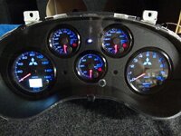
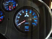
Test fitted gauges.
Close up of the counter sink.
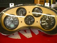
First things first, remove and disassemble your cluster. If this is difficult or heart breaking for you to do, you won't like what's coming up, turn back now.
You must be logged in to view this image or video.
Break it down to the parts shown above. Since I don't know the proper names for these items, I'll just call them (in order) glass, box, and trim. The box is (at least for the sake of this tutorial) facing you, with the bottom facing the bottom of the image.
I trashed all the extra pieces of my old cluster since I wouldn't be using them in my new one. I did make a note of my milage, just on the off chance I can input it into my new speedometer's odometer.
You must be logged in to view this image or video.
Next I ripped out the excess plastic trim around the old gauges and lights. Be careful to leave a bit of plastic trim around the edges of the old cluster. It's much cheaper to buy sand paper and get it closer to the vertical walls of the trim than it is to buy another cluster.
You must be logged in to view this image or video.
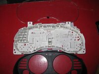
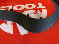
After I got the majority of the trim out, I went back with a drum sander and got the rest so it was flush with the walls. I also got a bit of the wall with the sander, but that's ok for my application because I will be using a texture coating on all the surfaces for an "OEM" look.
For the next step, I begged my boss to use the shop's scroll saw. If your boss is as forgiving as mine, he won't mind if you break a few blades. (I broke 3...
Not bad for my first time using a scroll saw though... Anyway, back to the tutorial)
You must be logged in to view this image or video.
You must be logged in to view this image or video.
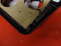
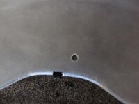
Cut out as much of the plastic back as you can while still retaining the supports (detailed in the second photo above). These will be holding your new gauge plate in place by pressure so you won't need glue or screws. Now that the back of the box is open, you'll notice that it's VERY flexible. Take care not to flex it too far, it will break.
Because I opted to flush my gauges into the cluster, I used 3/4" MDF (Medium Density Fiberboard) for my new gauge plate. After that last step, I got sidetracked and forgot to take pictures of shaping the MDF to fit the cluster, but maybe I can get enough words out here to give you the idea.
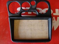
I cut down a piece of MDF a little larger than the trim piece. Then I did a lot of sanding on the belt sander to get it the approximate shape of the trim. Since the 2G cluster has a slight angle at the bottom of the box, I needed to bevel the bottom edge toward the back of the plate. This took a little guess work, a lot of luck, and a lot of test fitting. And honestly, a second piece of MDF and a "do over." Once the second piece of MDF was close enough for who it's for (me) I proceeded to further modify the box.
You must be logged in to view this image or video.
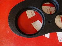
The "finished" plate, complete with trim tracing.
You must be logged in to view this image or video.
I did this using a very rough sanding disk chucked into my drill and a little downward pressure. Since the plate I used was 3/4" thick, I measured flush from the front side of the box down 3/4" on each support. I made a nice 3/4" template for this using scrap from my gauge plates. I drilled a hole into the scrap that was about the same diameter as the support posts, and then cut the piece roughly in half, bisecting the hole. Then I placed the box face side down onto a table, placed the template's groove onto each support, and made a mark. Easy as that! Then a little grinding, a little test fitting, a little grinding, a little test fitting, etc. Until the plate fit flush with the front face of the box.
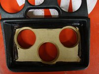
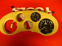
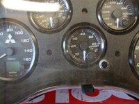
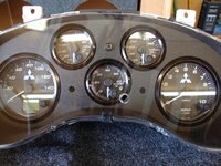
Next I plotted out where I wanted the gauges. This took a lot of time, and measuring, marking, erasing, remeasuring, remarking, etc. Finally, I ended up with this!
You must be logged in to view this image or video.
If I wanted to go through the headache of reforming another gauge plate, I would only do 4 gauges in the cluster. It's much more forgiving because it allows for more space between the gauges, and being 1/32" off in your measurements doesn't show as clearly in the final product.
After I got everything plotted, now it was time to beg the boss to use the drill press.
After permission was granted, I chose a hole saw that was as close to the diameter of the smaller gauges as possible. (Your forgiveness is required here as well, since I once again got sidetracked and didn't take pictures of the process. Those pesky customers, always wanting to buy stuff... ) I recommend using a tiny drill bit to get a pilot hole started for the center of each gauge location, and then stepping it up to something about 1/2 the size of whatever bit is in your hole saw. I clamped the gauge plate to the press, and began cutting holes. Once the small gauge holes were cut, I repeated the process on the larger holes, using the appropriate size hole saw of course. I highly recommend the use of a drill press for this portion, because if you don't get the holes exactly parallel to the plate, then your gauges won't sit right in the cluster. Also, don't be surprised if you can't find a hole saw the exact size of your gauges. My larger gauges slipped easily into place, but I had to sand out the holes for the smaller gauges a bit in order to get them to fit right.After all the holes were cut, it was time to create the counter sink to flush the gauges. Using a router, a flush bit, and a good assortment of bearings, I carefully routed the counter sink for each gauge. The key here is to find a large enough flush cutting bit, and a bearing that will make up for the leftover space between the chassis of the gauge and the overall diameter of the gauge. (This process would have been much easier had I not purchased surface mountable gauges. If you have straight body gauges, ex. 52mm face with a 52mm chassis, you won't need the router, but you will have to glue the gauges in place in the later stages of the build) Using more of the scrap from the gauge plates, I made test cuts, and fine tuned the depth of the router cut. Then, routed until my heart was content!
You must be logged in to view this image or video.
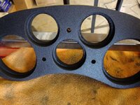
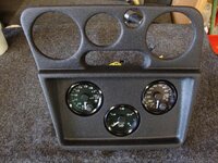
Test fitted gauges.
You must be logged in to view this image or video.
Close up of the counter sink.
Attachments
-
 Cluster001.jpg38.9 KB · Views: 4,809
 -
 Cluster011.jpg33.3 KB · Views: 4,292
 -
 Cluster010.jpg38.6 KB · Views: 4,360
 -
 Cluster009.jpg40.8 KB · Views: 4,848
 -
 Cluster007.jpg37.8 KB · Views: 4,328
 -
 Cluster006.jpg28.4 KB · Views: 4,315
 -
 Cluster005.jpg31.6 KB · Views: 4,356
 -
 Cluster004.jpg42.6 KB · Views: 4,392
 -
 Cluster003.jpg38.3 KB · Views: 4,498
 -
 Cluster002.jpg37.4 KB · Views: 4,683
 logo?
logo?


 Don't forget to plot and measure your gauge locations!
 ) youll want to level the surface with some sanding, a little body filler (AKA Bondo), and a LOT more sanding. Once youre satisfied with the curves of your corners, its time for texture paint!