Disclaimer: I am not responsible for anything done to your car/equipment. Use this information at your own risk. It is possible to damage components if you don't know what you are doing and don't use common sense. Keep in mind do these things at your own risk!
That being said, lets get onto the matter at hand:
This article explains how to remove connector pins from the ECU harness connectors (as well as other connectors.) You should note that a majority of the harness connectors employ replaceable pins.
The reason for this article is to help keep wire cutting/splicing to a minimum, not to mention a cleaner, more professional look. Typical uses for removing pins from connectors includes: clutch cut wire install, and knock light install, MAP sensor, MAFT, 90 ECU in 91-94 DSMs, among many others.
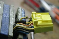
These particular pictures are taken of the smallest connector that goes into my 92 AWD's ECU.
Tools needed:
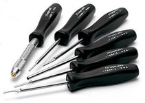
-very small/ jeweler's flat blade screwdriver
-needle nose pliers
-zip ties (optional)
Step 1
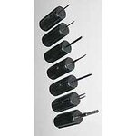
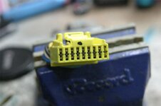
Identify which connector pin you want to remove. Then, using either the screwdriver or pliers, take out the black pin lock retainer that is directly above/below your pin.
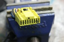
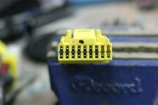
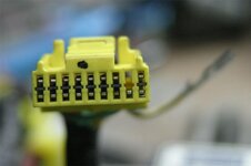
Now that the lock retainer is removed, look inside and see the yellow lock engaging the pin; holding them in. This picture shows the 2nd and 5th lock retainers removed.
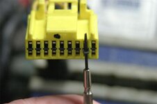
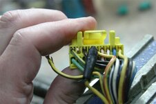
Every pin has a lock. The black lock retainer forces the locks against the pins. When it is removed the locks can be moved out of the way so the pin can be removed out the back (by pulling on the wire.) To remove the top pin slide the tip of the screwdriver against the bottom of the upper pin until it hits the lock.
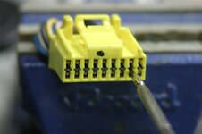
Pry the lock down, away from the pin, and pull on the wire to remove the pin. Do not pull the wire extremely hard, the pin should come out with minimal effort if the lock has been fully disengaged. Otherwise you'll just break the wire or connector.
It may take a few tries to pry the lock down far enough to let go of the pin. Also, don't pull the wire before you pry the lock down, because pulling on the wire locks the lock into the pin. (I pushed the wire into the connector just a tad and then used the screwdriver to pry the lock down and then pulled on the wire.)
It is extremely difficult to get the original wire out of the pin, so I recommend you not mangle the pin up by trying. Simply pry open the tangs that are clamped onto the insulation and then put your wire under it and clamp the tangs down with your wire in there.
Since I was doing the DSMLink clutch-cut wire install, I had to completely remove the original wire as per DSMLink instructions. I broke the original wire off at the pin and installed my own wire.
In this picture you will see that I doubled the wire over inside the pin. I did this to reduce the wire being inadvertently pulled out and it gave the tangs more to clamp onto. Bending the tangs more than necessary and bending them repeatedly will fatigue them and they will break off, so be careful.
If you decide to double over the wire like I did, make sure that you make the loop small because if it is too long it will interfere with the lock when you reassemble the pin into the connector.
Finally observe the orientation of the other pins and insert your pin correctly into the connector.
The result is a nice, factory-looking, clean install; no splices, electrical tape, etc. You will see that I looped the original wire back into the harness cover and zip tied the whole assembly to reduce the likelyhood of any extra stress on the wires when I install the ECU and then work it back into the place it goes.
I also added a wire to the pin directly to the left of the orange wire I installed in this "How-to."(That one is for the knock light I installed months ago.) I bet you didn't even notice until I mentioned it because of the clean look.
I hope this helps at least SOME people, and remember most connectors have replaceable pins. The clutch switch has a rear-release lock(put screwdriver in next to wire and then pull wire to remove pin. That connector has standard blade/socket connectors. Just remove the insulation on any socket, crimp it on a wire, and install into connector in place of original(or whatever your procedure calls for.)
If this info helps you I'd be glad to hear about it. Please feel free to PM me and let me know you thought this was a good tech article or not.
Extra pics: 1 ,2 ,3 ,4 ,5 ,6
Good luck,
-Jesse
That being said, lets get onto the matter at hand:
This article explains how to remove connector pins from the ECU harness connectors (as well as other connectors.) You should note that a majority of the harness connectors employ replaceable pins.
The reason for this article is to help keep wire cutting/splicing to a minimum, not to mention a cleaner, more professional look. Typical uses for removing pins from connectors includes: clutch cut wire install, and knock light install, MAP sensor, MAFT, 90 ECU in 91-94 DSMs, among many others.
These particular pictures are taken of the smallest connector that goes into my 92 AWD's ECU.
Tools needed:
-very small/ jeweler's flat blade screwdriver
-needle nose pliers
-zip ties (optional)
Step 1
Identify which connector pin you want to remove. Then, using either the screwdriver or pliers, take out the black pin lock retainer that is directly above/below your pin.
You must be logged in to view this image or video.
Now that the lock retainer is removed, look inside and see the yellow lock engaging the pin; holding them in. This picture shows the 2nd and 5th lock retainers removed.
You must be logged in to view this image or video.
Every pin has a lock. The black lock retainer forces the locks against the pins. When it is removed the locks can be moved out of the way so the pin can be removed out the back (by pulling on the wire.) To remove the top pin slide the tip of the screwdriver against the bottom of the upper pin until it hits the lock.
You must be logged in to view this image or video.
Pry the lock down, away from the pin, and pull on the wire to remove the pin. Do not pull the wire extremely hard, the pin should come out with minimal effort if the lock has been fully disengaged. Otherwise you'll just break the wire or connector.
It may take a few tries to pry the lock down far enough to let go of the pin. Also, don't pull the wire before you pry the lock down, because pulling on the wire locks the lock into the pin. (I pushed the wire into the connector just a tad and then used the screwdriver to pry the lock down and then pulled on the wire.)
You must be logged in to view this image or video.
It is extremely difficult to get the original wire out of the pin, so I recommend you not mangle the pin up by trying. Simply pry open the tangs that are clamped onto the insulation and then put your wire under it and clamp the tangs down with your wire in there.
Since I was doing the DSMLink clutch-cut wire install, I had to completely remove the original wire as per DSMLink instructions. I broke the original wire off at the pin and installed my own wire.
In this picture you will see that I doubled the wire over inside the pin. I did this to reduce the wire being inadvertently pulled out and it gave the tangs more to clamp onto. Bending the tangs more than necessary and bending them repeatedly will fatigue them and they will break off, so be careful.
You must be logged in to view this image or video.
If you decide to double over the wire like I did, make sure that you make the loop small because if it is too long it will interfere with the lock when you reassemble the pin into the connector.
Finally observe the orientation of the other pins and insert your pin correctly into the connector.
You must be logged in to view this image or video.
The result is a nice, factory-looking, clean install; no splices, electrical tape, etc. You will see that I looped the original wire back into the harness cover and zip tied the whole assembly to reduce the likelyhood of any extra stress on the wires when I install the ECU and then work it back into the place it goes.
You must be logged in to view this image or video.
I also added a wire to the pin directly to the left of the orange wire I installed in this "How-to."(That one is for the knock light I installed months ago.) I bet you didn't even notice until I mentioned it because of the clean look.
I hope this helps at least SOME people, and remember most connectors have replaceable pins. The clutch switch has a rear-release lock(put screwdriver in next to wire and then pull wire to remove pin. That connector has standard blade/socket connectors. Just remove the insulation on any socket, crimp it on a wire, and install into connector in place of original(or whatever your procedure calls for.)
If this info helps you I'd be glad to hear about it. Please feel free to PM me and let me know you thought this was a good tech article or not.
Extra pics: 1 ,2 ,3 ,4 ,5 ,6
Good luck,
-Jesse
Last edited by a moderator: