pearl4gtsi
15+ Year Contributor
- 216
- 2
- Jul 17, 2004
-
yonkers,
New_York
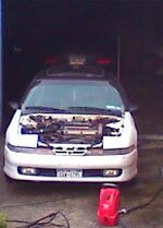
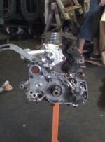
hey all this is my tech on building my motor.
i got the weisco 9.0 compression pistons(.040 overbore) and manley connecting rods. i got the block decked, bored, hot tanked, and all threads checked at my machine shop. i also had the entire rotating assembly balanced. this includes: factory crankshaft, fidanza 8lbs flywheel, act 2600 clutch, disc and throw out bearing, pistons, rods, and front timing belt gear.
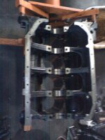
i started cleaning the crank very well(as directed by the machine shop) with carb cleaner, compressed air and a good, clean rag. i installed the main bearings on the block and the main bearing caps. i then used vaseline and lubed all bearings. Do not grease the part of the bearing where the sit in the block and caps. only on the crank surface. installed arp main studs using arp moly lube on the threads. these only went hand tight.
i used new crush o-rings on well cleaned oil squirters and installed in block, torquing to 25ft.lbs. installed crank and main caps. hand tightened nuts in three steps: hand tight with ratchet, 40ft.lbs with torque wrench, 60ft.lbs with torque wrench, and then a final once over at 60. i used the torque sequence in the factory service manual. once in and tight, i rotated crank 4-5 rotation to check for binding. measured backlash and endplay. both withing spec.
i also took measurements of the outside diameter of the piston, inside diameter of the cylinder bore, and cylinder bore taper. all amazingly perfect. this is my check on the machine shop work quality and the chance of mass production mess ups. this will ease my worries when i start the motor for the first time.
intalled pistons on connecting rods. took the piston rings and placed them in the cylinder bore. I thenused the piston head to level it out. using a feeler gauge, measured the piston ring gap. again, nice and tight in spec. i put the rings on the pistons and placed the gap in the 1st and 2nd ring 180 degrees from each other. as well with the oil rings. placed piston in piston ring compressor and tightened. iused vaseline to lube the cylinder walls well. On top of that, i also went over the vaseline with a little fresh motor oil. makes good for a slippery surface (learned this one doing automatic transmisson rebuilds). placed piston(while still in ring compressor) in the block and using the butt end of plastic hammer, tapped piston into block. once the skirt of the piston starts to go into the cylinder, i stopped and tapped down all around on the ring compressor to make sure it is fully seated on the block. the best method to do this is a block of wood. this is to insure that the ring compressor is fully seated on the deck surface so the piston rings don't pop out. continued tapping piston into cylinder, fit like a glove!
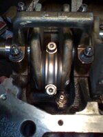
i tapped piston all the way down to seat the connecting rod on the crank journal and had my friend guiding it the entire way. then it was time to place the cap on connecting rod. make sure that the notches for the bearings go on the same side when installing the cap. again used arp moly lube on the connecting rod bolts, as they come arp. tightened in the same three steps as above only ending at 65ft.lbs.
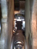
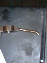
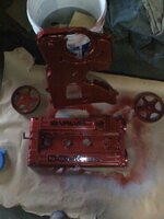
with just the one piston in, i rotated the crank and felt something weird. i then remembered reading a post where the oil squirters may come in contact with my particular piston. couldn't find a mirror, but i found a nice long carving knife with a mirror finish and used that. i saw the piston at bottom dead center come in contact with the oil squirter. NOT GOOD!! . i removed all oil squirters and modified them using a dremel with a cutoff wheel. I removed about 1/8" off the end.
the one that got hit by the piston had to be bent back into shape because when we put it back in, it then came in contact with the crank counterweight. just used a propane torch to heat and bend. then finished off installing the other three pistons into the block and checked all the squirters one last time. the cut was perfect. great note to somebody purchasing those pistons.
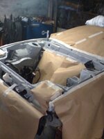
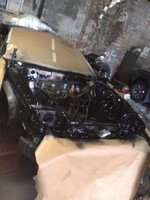
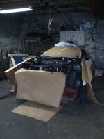
stopped there as it was getting late, but will continue next weekend and post more. i intend to post the entire build from now to startup.
i included some pictures of the build, and again will continue to do so with the build. i hope my experiences being written down will be useful to any one.
i got the weisco 9.0 compression pistons(.040 overbore) and manley connecting rods. i got the block decked, bored, hot tanked, and all threads checked at my machine shop. i also had the entire rotating assembly balanced. this includes: factory crankshaft, fidanza 8lbs flywheel, act 2600 clutch, disc and throw out bearing, pistons, rods, and front timing belt gear.
i started cleaning the crank very well(as directed by the machine shop) with carb cleaner, compressed air and a good, clean rag. i installed the main bearings on the block and the main bearing caps. i then used vaseline and lubed all bearings. Do not grease the part of the bearing where the sit in the block and caps. only on the crank surface. installed arp main studs using arp moly lube on the threads. these only went hand tight.
i used new crush o-rings on well cleaned oil squirters and installed in block, torquing to 25ft.lbs. installed crank and main caps. hand tightened nuts in three steps: hand tight with ratchet, 40ft.lbs with torque wrench, 60ft.lbs with torque wrench, and then a final once over at 60. i used the torque sequence in the factory service manual. once in and tight, i rotated crank 4-5 rotation to check for binding. measured backlash and endplay. both withing spec.
i also took measurements of the outside diameter of the piston, inside diameter of the cylinder bore, and cylinder bore taper. all amazingly perfect. this is my check on the machine shop work quality and the chance of mass production mess ups. this will ease my worries when i start the motor for the first time.
intalled pistons on connecting rods. took the piston rings and placed them in the cylinder bore. I thenused the piston head to level it out. using a feeler gauge, measured the piston ring gap. again, nice and tight in spec. i put the rings on the pistons and placed the gap in the 1st and 2nd ring 180 degrees from each other. as well with the oil rings. placed piston in piston ring compressor and tightened. iused vaseline to lube the cylinder walls well. On top of that, i also went over the vaseline with a little fresh motor oil. makes good for a slippery surface (learned this one doing automatic transmisson rebuilds). placed piston(while still in ring compressor) in the block and using the butt end of plastic hammer, tapped piston into block. once the skirt of the piston starts to go into the cylinder, i stopped and tapped down all around on the ring compressor to make sure it is fully seated on the block. the best method to do this is a block of wood. this is to insure that the ring compressor is fully seated on the deck surface so the piston rings don't pop out. continued tapping piston into cylinder, fit like a glove!
i tapped piston all the way down to seat the connecting rod on the crank journal and had my friend guiding it the entire way. then it was time to place the cap on connecting rod. make sure that the notches for the bearings go on the same side when installing the cap. again used arp moly lube on the connecting rod bolts, as they come arp. tightened in the same three steps as above only ending at 65ft.lbs.
with just the one piston in, i rotated the crank and felt something weird. i then remembered reading a post where the oil squirters may come in contact with my particular piston. couldn't find a mirror, but i found a nice long carving knife with a mirror finish and used that. i saw the piston at bottom dead center come in contact with the oil squirter. NOT GOOD!!
. i removed all oil squirters and modified them using a dremel with a cutoff wheel. I removed about 1/8" off the end. the one that got hit by the piston had to be bent back into shape because when we put it back in, it then came in contact with the crank counterweight. just used a propane torch to heat and bend. then finished off installing the other three pistons into the block and checked all the squirters one last time. the cut was perfect. great note to somebody purchasing those pistons.
stopped there as it was getting late, but will continue next weekend and post more. i intend to post the entire build from now to startup.
i included some pictures of the build, and again will continue to do so with the build. i hope my experiences being written down will be useful to any one.