The Top DSM Community on the Web

For 1990-1999 Mitsubishi Eclipse, Eagle Talon, Plymouth Laser, and Galant VR-4 Owners. Log in to remove most ads.

Please Support RTM Racing
Please Support ExtremePSI

2G Bad TPS....AGAIN?

This site may earn a commission from merchant
affiliate links, including eBay, Amazon, and others.

This site may earn a commission from merchant affiliate links, including eBay, Amazon, and others.

ChrisFlo

15+ Year Contributor
412
2
Aug 29, 2004
Tucson, Arizona
I have a 98 gst.

After months of problems I finally gave in and took my car to an auto shop. They told me I had a bad TPS sensor, so I gave the go ahead to replace it.

However, the car has once again begun acting up on me. I'm getting idle surge, with the car jumping between 1k and 2.5k. I first thought it was the result of a bad MAS, but after closer inspection I'm starting to think that once again, I somehow ended up with another bad TPS. Below are fixes I've tried, as well as symptoms after various tests.

Fixes tried

New spark plugs and wires
"New" TPS (from shop)
Two ISC's tested
Two MAP sensors tested
Biss screw adjustment
Vacuum/boost leak test
Two batteries tried
fuel pump inspection

Symptoms and tests

1. With the car running, and just the TPS unplugged, the car holds a steady idle but that idle sits at the 2k range.

2. When plugging the TPS back in, the car begins surging between 1 and 2.5k rpms

3. With the TPS plugged in, I tried unhooking the ISC. No change. Still surging.

4. With the TPS plugged in, I tried unhooking the MAS. The car almost dies, as it should.


I'm pretty convinced that another TPS is needed following these results. Any advice that can help me get this car up and going will be greatly appreciated.
 
If you got some time id take out your ecu and check to see if you got any leaking caps. I had some leaking caps that where messing with sensors and stuff. Like at wot my tps readings would jump around crazy and i had pretty bad idle surge. I threw in a good ecu and the idle is nice and smooth now.
 
As far as I can tell, the ECU looks fine. I'll post pics. Anything else?

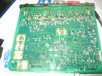
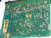
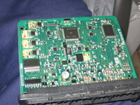
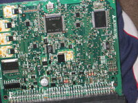
Here are the pics. There does seem to be some kind of clear liquid coating over the entire ECU, but I believe that is normal...right?
 

Attachments

  • Picture 001.jpg
    Picture 001.jpg
    80.1 KB · Views: 1,094
  • Picture 003.jpg
    Picture 003.jpg
    73.4 KB · Views: 1,070
  • Picture 004.jpg
    Picture 004.jpg
    75.2 KB · Views: 1,013
  • Picture 005.jpg
    Picture 005.jpg
    99.3 KB · Views: 1,015
Last edited by a moderator:
Hey Chris did you ever figure out what the problem was? My CEL is on and I'm getting code p0120 which is the TPS. So I bought a TPS from a store on ebay who is a positive reputation for selling remanufactured DSM parts. I put the new TPS on 6 days ago and the problem has not gone away. My CEL is still on even after disconnecting the battery. I too get the idle surges when my car is cold but mine only jumps to 1500/2000. My safcII Throttle % stays at 100%.
 
I am also getting this probelm. I had a cel code for my tps, changed it, connected battery again and it was still showing when the car was idle that it was around 97% on my logger. :confused:
 
Hey Chris did you ever figure out what the problem was? My CEL is on and I'm getting code p0120 which is the TPS. So I bought a TPS from a store on ebay who is a positive reputation for selling remanufactured DSM parts. I put the new TPS on 6 days ago and the problem has not gone away. My CEL is still on even after disconnecting the battery. I too get the idle surges when my car is cold but mine only jumps to 1500/2000. My safcII Throttle % stays at 100%.

My car is having problems starting but also i replaced the TPS and my throttle position % on my SAFC says 100% all the time as well. We need a fix. Maybe another or bad sensor or maf/mas/barro meter problem? Shop is printing me out of list of cels. So i will report back soon.
 
RREs# Eclipse 2G Turbo 1G Throttle Body Swap
Closed TP Switch and TP Sensor Adjustment [2G]
1. Disconnect the connector of the TPS.
2. Connect ohm meter between terminals 3 and 4.
3. Insert a feeler gauge with thickness 0.45mm (.0177 in.) between the throttle stop and the throttle lever.
[Fold a piece of paper in half 4 times if you don't have the feeler -Ed.]
4. Loosen the TPS mounting bolts. Turn the TPS all the way counter
clockwise.
5. Check for continuity in this condition.
6. Slowly turn the TPS clockwise until the point where continuity and
non-continuity is found (pins 3 and 4).
7. Tighten the TPS mounting bolts.
8. Check the voltage between pins 2 and 4 of the TPS with the ignition
switch on, but the engine not started.
9. Standard value: 400 - 1000 mV
10. Remove the feeler gauge
You must be logged in to view this image or video.
 
Yay, finally somebody posts the right information.

Why does the TPS has anything to do with surging on a 2G? Because it has the IPS and without the ECU seeing the throttle closed from the IPS it doesn't check for decel cutoff RPMs.

It's not the TPS that causes the idle to be too high so it's not really the cause of the surging but if the IPS isn't showing the throttle closed the ECU doesn't check that the idle is too high and you just get the high idle not the surging.

Find the air leak to fix the high idle if the BISS won't bring the idle down to 750 RPM.
 
A friend came over today who owns a red Evo and Evoscan with a mini laptop. We swapped out between the two used TPS. No change in the reading, still says 100% unless unconnected, which results in 0% reading. Is it possible both TPS are bad? We checked the resistance and one of the TPS seems to be good. Other than that, We played with it plenty while it was connected and no matter where the position of the TPS spring was... it didn't change from 100%.

Any other Opinions? Should I just go buy a new TPS and see if it changes anything then return it? Or what? I'm running out of cars to use since the brakes went out on my DD 97 Avenger :cry:

I'd rather spend money to fix my Eclipse rather than fix the beater. Local DSM tuners, hit me up. Veterans... lend me a hand.
 
No change in the reading, still says 100% unless unconnected, which results in 0% reading. Is it possible both TPS are bad? We checked the resistance and one of the TPS seems to be good. Other than that, We played with it plenty while it was connected and no matter where the position of the TPS spring was... it didn't change from 100%.

Explain what you were measuring?
You could have a good TPS is you somehow damaged the wiring. For example a bad ground to the TPS would cause the output voltage to be stuck at 5v.
 
Explain what you were measuring?
You could have a good TPS is you somehow damaged the wiring. For example a bad ground to the TPS would cause the output voltage to be stuck at 5v.

Resistance and Voltage. So the harness that plugs into the TPS could be damaged and making it only read 0% or 100%? I thought maybe if I somehow didn't have the correct TPS sensor for my car, could that cause this? Like maybe from a 1g or another car?

Also, I do have a MDP sensor from a Galant or something I believe on my car from eBay. Would that affect anything? It matched up and looked identical, so I used it. I know I know... I'm cheap. But I have money now, so help me fix it please.

I'm also up for the idea of upgrading the TB itself to a 1g TB. If the TPS was Already re-calibrated prior to removal, If I installed the TB would everything be okay?
 
See the picture of the TPS above, that TPS has 4 pins since it's a 2G TPS. The 1G TPS has 3 and are missing pin 3 which is the IPS signal.

The other pins are for the sensor +5v power (1), TPS output (2), and sensor ground (4). They are to the internal potentiometer and are connected to form a voltage divider that varies between 0v and 5v.

When you test the TPS you measure the total resistance between pins 1 and 4, and that the resistance varies smoothly as you turn it between pins 1 and 2 as well as 2 and 4. With the TPS disconnected and the ignition off you should measure 0 ohms between pin 4 and chassis ground and with the ignition on 0v on pin 4 and about 5v on pin 1. Pin 2 is undefined and pin 3 should have something > 3v (whatever the IPS pull up voltage on your ECU is)

As described above, adjusting a 2G TPS is based on rotating the TPS until the IPS switch point is found. If you change throttle bodies you can adjust that off the car.
 
Could an ECU cause the TPS to read 100% constantly.

Sure, it could but it would be unusual. The typical case would be because the sensor ground was blown but you say yours is flawless.

Actually measuring the TPS output voltage would nail question pretty quickly.
 
We did a TON of testing. Could a shorted out TPS wire cause the 100% or a bad TPS connector? Because honestly, this car use to still be drivable even with the 100% reading. Now... its just horrific and I refuse to drive it untill this is fixed.
 
I'm sorry. It doesn't really matter if it works while broken before or not. If you don't understand how to identify the root cause of the problem then let us know but I've pretty much covered what it should do and now it's up to you to check and diagnose the problem.

Telling us that you've done a TON of testing without spelling out exactly what you did and the results is useless to us because we have no idea what you've done.

I hope you figure it out.
 
I know your trying to help, you have given me a TON of information so far. We used the ohmeter, we tested for resistance and voltage as stated above. There is voltage (4.23 I think), the TPS is getting a signal but like I said it reads 100% or 0% when disconnected.

Would I have to puncture the wires with a couple pins in the connector, WHILE the TPS is connected, in order to get a reading while the car is on the ON position? I dont want to hack the wires up.

It might be easier to just replace the entire wiring that goes from the ECU to the TPS. Any specific wires I should Use? I'm guessing there are 4 or 5, one for the ground.

Could the TPS connector itself be bad or shorting out? Because I'm starting to believe it's the wiring or the connector because we have continuity and we found the drop off point for where the TPS should be positioned via rotating it.

Hope this helps, I did the testing with a friend and I am not skilled in this part or wiring or the electrical aspect. Bolt-On's is where I excel. Thanks for all input and Opinions. Wish there was a YouTube video...
 
I know your trying to help, you have given me a TON of information so far. We used the ohmeter, we tested for resistance and voltage as stated above. There is voltage (4.23 I think), the TPS is getting a signal but like I said it reads 100% or 0% when disconnected.

Would I have to puncture the wires with a couple pins in the connector, WHILE the TPS is connected, in order to get a reading while the car is on the ON position? I dont want to hack the wires up.

How are you getting that voltage if your not able to measure while the TPS is attached?

The dealership has a break out harness for measuring, I either pass a small wire through the rubber boots on the TPS connector until it hits the connector or measure at the ECU end where the pins are a little more exposed or via the sensor check page on the SAFC.

The measurements I referenced above were all with the TPS disconnected except for measuring the actual TPS output voltage. I wanted you to check the harness and the TPS individually. What I want to hear back is the specifics for each measurement.

So broken down:

These are with the TPS detached from the TB and disconnected for the harness.
The resistance between pins 1 and 4.
The resistance between pins 1 and 2. Does the resistance change smoothly as you rotate the part that mates with the throttle shaft?
The resistance between pins 2 and 4. Does the resistance change smoothly as you rotate the part that mates with the throttle shaft?

These are measuring the harness with the TPS disconnected and the ignition off.
The resistance between pin 4 and the chassis ground.

With the ignition on: (be careful to not touch pins together)
The voltage between pin 4 and chassis ground.
The voltage between pins 1 and 4.
The voltage between pins 2 and 4.

Testing basic electrical functions is something you really need to master since more and more of the systems in a car are electronic rather than mechanical.

If you don't have the Factory Service Manuals you might want to find them online and look at the MPI diagrams while your working on this.
 
My ECU was damaged, I sent it in to Steve. He fixed it, now my car runs great. Just because an ECU looks good, doesn't mean it's good. Mine looked MINT and still had a blown capacitor. Eventually leaking on the board and causing a few burn marks. Steve being the boss that he is, fixed it and shipped it back prompt.

If replacing the TPS does not fix it, send your ecu to Steve for a check up. :thumb:
 
When you took the pic's the capacitors weren't leaking, and then the finally started to leak? What a pain in the ass, I was thinking you maybe had the wrong aftermarket TPS seeing as I had so many problems with the aftermarket versions I went and got a working used on for my 1G. Damn ECU problems are hard to figure out sometimes, what a pain in the ass.
 
Support Vendors who Support the DSM Community
Boosted Fabrication ECM Tuning ExtremePSI Fuel Injector Clinic Innovation Products Jacks Transmissions JNZ Tuning Kiggly Racing Morrison Fabrications MyMitsubishiStore.com RixRacing RockAuto RTM Racing STM Tuned

Latest posts

Build Thread Updates

Vendor Updates

Latest Classifieds

Back
Top