The Top DSM Community on the Web

For 1990-1999 Mitsubishi Eclipse, Eagle Talon, Plymouth Laser, and Galant VR-4 Owners. Log in to remove most ads.

Please Support Kiggly Racing
Please Support Fuel Injector Clinic

2g Battery Relocation

This site may earn a commission from merchant
affiliate links, including eBay, Amazon, and others.

This site may earn a commission from merchant affiliate links, including eBay, Amazon, and others.

DSM4LIFE-AWD

10+ Year Contributor
322
10
Aug 6, 2009
Trois-Rivieres, QC_Canada
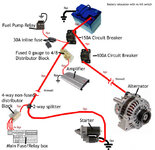
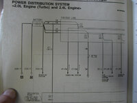
After reading and searching all day long I came up with this draw.

You must be logged in to view this image or video.


I still dont know if its the way to go ... Some threads say that you need to put an other 80 amp fuse near the starter ? Some say that the circuit breaker need to be after the switch ?

Well I used the diagram that came with the moroso kill-switch to do this picture and I want to know if I miss something before I put fire in my dsm ...

Thanks
 
If I recall correctly, the alternator has a 100 amp fuse, not 80. You can group the 4 small wires coming out of the fuse box and tie them together as one 4G wire. Then all you'll need is a distribution block that can take 2 x 4G wires IN and one 1/0G wire out.

I'm planning to relocate my battery too, getting tired of the damn corrosion in the engine bay.
 
Too late, it's been installed for a while, just never actually hooked it up to kill power.
Will upgrade to V3 in the future.
Thanks.
 
Thanks a lot Snowborder714, just what I wanted to know !

I don't think your fuse has ever pop when using a 200amp fuse (near alternator) I know it must not pop but 200amp seems to be a bit high ... I also don't get why you put a second circuit breaker after the kill switch, the one at the battery should not do this job ?
 
The car hasn't been started yet, so we haven't popped any fuses yet. We went with that high for the fuse because the amperage is much higher than stock.

The reason for the fuse and circuit breaker combination was based on this post from twicks69. We originally had a fuse inline between the kill switch and the distribution block, but after consulting with twicks69, he suggested it was overkill. Now, the whole setup is overkill in general, but that's just how we do things.
http://www.dsmtuners.com/forums/151770687-post71.html
 
Im going to relocate my batt. and all i plan on doing is putting the batt. in the trunk, fuse it, run a 1/0 wire to the engine bay into a power distrubution block and just hook the wires that went to the batt. into the distribution block.
 
Subscribed*

I have already relocated my batt to the trunk but after taking the car to the track and not passing tech, I just picked up the Moroso battery kill switch and for my own reason's I also picked up Battery Jumper Terminals. Both will be mounted to the rear bumper. Is there anything special I need to know for installing the battery jumper terminals.

Both purchased from Summit Racing
http://www.timskelton.com/lightning/race_prep/weight/images/moroso_switch.jpg
http://www.timskelton.com/lightning/race_prep/weight/images/accessory_terminals.jpg
 
I've been searching for a good battery relocate thread. I chose to post my question here rather than in other threads because this is the best battery relocation thread I can find on this board and I'd like to see more info for systems that are less-than overkill for the for sub-600hp weekend warriors. Kill switch-less setups are mentioned here, but not expanded upon. That's what I'm trying to do.

I respect that the "overkill" system for the car snowboarder714 built has got some serious shit installed in it to need a 200A electrical system. I don't compete in car audio events, and I don't compete in sanctioned drag racing events or road race either, so I don't even really need the cutoff switch. I do go to the occasional friday night street shootout at my local dragstrip whenever the weather's good (and if I don't have a big hole in my transmission), but their tech is seriously lax. All I need is a safe electrical system that goes "tick" in such a way when overloaded or shorted out that I can fix the problem instead of searching for some bastardized proprietary fuse at 7:00 PM on a Sunday in order to make it home.

The use of so many fuses in that system above seems excessive to me. I'm not trying to be closed minded and shooting stuff down that others have posted by asking these questions, I'm sure there's probably a need for it on that car. I'm inviting discussion in an attempt to understand this better before drilling any more holes or buying more stuff that I don't need. Here are my questions...

1) Why would there be a need to install an in-line fused distributor block as a power supply for yet another fuse box? Everything in the box is already fused. The car's main 100A fuse is the first thing in-line in that box, and it steps that down to smaller fuses from there for individual components. Not sure if this was the unnecessary redundant fuse mentioned before?

2) Why is there a need to install a fuse on the starter? It's not fused from the factory on any car I've ever seen, so all I can gather from the image above is that the starter doesn't pull enough amperage to pop that big of a breaker if the starter wire gets grounded out. ?

3) Why fuse the alternator? The main circuit breaker (with cutoff switch) or secondary (w/o cutoff switch) breaker should protect it.

I have DSMLink v2, and losing power with v2 is bad, I know. I don't want to end up stranded because some idiot turned my battery off thinking he's funny, so I don't want the kill switch. We all know too many of those already. I don't want to drill a hole in the body or tail light, or affix kill switch stickers on the body for a remote switch. I just need to get this thing running with a safe setup that works properly as I haven't driven it in over 16 months now and I miss the hell out of it.

So here's what I've got going... Can someone critique this?

I made this graphic to represent what hardware I already have. There are some omitted items from the diagram including engine grounds, secondary wiring, or my Dynatek ignition box (which will be connected at the non-fused 4-way distributor in the engine bay). Every aftermarket electrical component like the fuel pump relay, Dynatek and stereo equipment already has an inline fuse... well, the audio amplifier doesn't but I have a fused distributor block and it's pictured. So the main question I have once my previous fuse questions are cleared up would be...

4) Does it matter or is it better if I connect the secondary 100A (alternator) relay directly to the + battery terminal rather than daisy-chaining it through the main breaker? Or is it all the same?

Thanks for taking the time to look at my scribbles and consider my questions. You're helping me build a better DSM.
 

Attachments

  • Jafros2gbatteryshit.jpg
    Jafros2gbatteryshit.jpg
    64.8 KB · Views: 10,622
The setup snowborder714 described is the one in my car.

1. I needed a distribution block. The one that fit my setup best happened to be fused so I got it. Not necessary at all, it just happened to fit the bill.
2. If you're talking about fusing the starter by use of the distribution block see answer to #1.
3. Safety (and yes I know it's overkill). Fuses work better and faster than circuit breakers. See the link in post 9 for more info. The circuit breaker is in there just for double protection and for convenience so I can easily cut power to the alternator when working near it. Note: the kill switch will NOT cut power to the alternator wired in the above manner. For that you would need to get a heavy duty relay (such as Painless #50105). I couldn't justify the price of that for what it accomplishes.
4. Since you don't have a kill switch, I would rather connect the alternator straight to the battery unless it's a hassle. It would be in my case because of the battery terminals I have. And instead of using a 100A cb I would use a fuse there for the reasons mentioned above.

Besides that the picture looks ok to me. You can back off some things if you don't want to be overkill, like the starter wire doesn't have to be 0ga. and the distribution block doesn't have to be fused. It was just easiest for me to be a large quantity of 1/0 wire (which totaled to 44 ft. used!) to use for everything.

I think that covered everything you questioned. My relocation is 99% complete so let me know if you have more questions or need pictures of anything. I feel I managed to make the relocation clean, well done, and reliable so it works for me. I haven't powered it up yet though so we'll see!
 
Wow, thanks for the quick answer.

About the alternator...

Edit: nevermind, you were referencing kill switches and snowboarder's image. Gotcha.

Edit: ...and #2 was tied to the answer for #1. Thanks again.
 
Wired the way OP stated, will cut off the power to the fuel pump rewire, right?
Therefore, cutting fuel supply to the car and shutting off?
 
Okay I got the battery box shelf welded into the trunk and the holes cut for the 1ga power/starter and 4ga alternator wires. I found great locations for all the fuses and distribution blocks in the front of the car and that's all squared away. But I've run into something I need clarified.

Alternator wires:
There are 4 wires (actually a 5th for HVAC spliced into one pair) coming from the main fuse box. 2 wires break off of the 100A main alternator fuse to charge the battery, and 2 wires isolated on the post next to it (that have the wire for HVAC) that draw power for everything else. Normally, both of these pairs of wires bolt to the battery's + terminal and serve to both charge the battery and power all the electrical stuff. But the alternator doesn't connect directly to the battery. It appears to go through the 100A fuse and whatever other circuits its charged-wire terminal post is connected to. I didn't take it apart any further than this to check, but the wiring diagram seems to indicate that it's not on an isolated circuit.

The 2 alternator wires coming from the alternator itself, that bolt to the top post of the 100A fuse seem to connect to a plate that goes off to power other things. The wire from the other side of the fuse that runs back to the battery is isolated from other circuits or the other 2 wires that connect to the battery. The other 2 battery wires don't involve the alternator circuit at all. I guess this is because most components work Key-On-Ignition-Off, and some work only Key-On-Ignition-On.

Where my confusion lies is here:

A) do I use 2 of the wires on the alternator circuit to connect to the fused 4ga alternator feed to the battery, and the other 2 in the distribution block?

Seems to me like that could create a loop if the alternator circuit powers anything else. I looked at the diagrams but can't really tell what junctions are where and on which side of what fuse. Probably because I'm an idiot. I never claimed to be an electrical engineer.

B) Do I run the all-the-way-to-the-battery 4ga cable all the way to the charge post of the alternator, bypassing the factory alternator wires altogether and connect all 4 of these white wires to the terminal block while disconnect the factory alternator wires from the terminal post...

C) could I disconnect the factory alternator wires (the slighty yellowed big ones in the pic below), replacing the bolt on the 100A fuse, and run those 2 8ga wires directly into the all-the-way-to-the-battery wire's fused link? I have a 80A fuse there. Not 100A. This is sort-of a variation from B. With this setup, all 4 white 8ga wires go directly into the distributor block so all circuits could draw power, but the purpose for that 100A fuse on the fuse box lid would be lying. The alternator would bypass the whole fuse box just like B.

All of my connections are made directly below the fuse box and C would be really easy, but I've never done this and hate how hot fire gets.
 

Attachments

  • CIMG4089.jpg
    CIMG4089.jpg
    52.4 KB · Views: 2,107
  • CIMG4090.jpg
    CIMG4090.jpg
    66.4 KB · Views: 2,143
  • CIMG4091.jpg
    CIMG4091.jpg
    53 KB · Views: 1,981
  • CIMG4092.jpg
    CIMG4092.jpg
    49.9 KB · Views: 2,005
  • CIMG4093.jpg
    CIMG4093.jpg
    38.8 KB · Views: 1,904
more room in engine bay for intercooler piping ect ,takes less time to remove when its in the rear hatch, looks better less clutter in engine bay, more air flow, sometimes wieght distribution for autocross all depends
 
That sucks.And how much is this throttle body?

Free, considering it's a 1g.

Come on man, you know that's not even relevant to the thread. I'm looking for feedback from someone who's done this. Not someone that's debating its usefulness. Anyone who's attempted this has a reason for doing it. You don't just relocate a battery for the hell of it.

OK, got my answer. Thought I'd share.

It's B or C. Either one works.

The 100A Alternator fuse indeed powers other systems. It makes no difference whether those items get their draw from the battery or the alternator. So I'm hooking up all 4 white wires to the distributor block, un-bolting the alternator wires from the fuse (replacing the bolt and leaving the fuse there), running those 2 wires through the 4ga drop to the battery, and calling it a day.
 
Support Vendors who Support the DSM Community
Boosted Fabrication ECM Tuning ExtremePSI Fuel Injector Clinic Innovation Products Jacks Transmissions JNZ Tuning Kiggly Racing Morrison Fabrications MyMitsubishiStore.com RixRacing RockAuto RTM Racing STM Tuned

Latest posts

Build Thread Updates

Vendor Updates

Latest Classifieds

Back
Top