

The idea is to swap a 98-99 N/A 4G64 Spyder's ECU with a 95-99 turbo ECU. In addition, swapping the stock high impedence 275cc injectors with 450cc low impedence injectors found on turbo 2G models. The turbo ECU expects 450 cc injectors and may offer more timing and aggressive fuel maps. This mod will also include the addition of a turbo model throttle body. If you plan on turbocharging your Spyder, the knock sensor will help protect your engine by retarding timing if serious knock occurs. *Note that 96-97 4G64 Spyders have distinct differences and may need additional wiring not covered in this guide.
Parts list and prerequisites:
1. 95-99 2G turbo ECU. With Studs/Bolts. The N/T bolts are to short.
2. 450cc low impedence injectors from a stock Eclipse turbo car.
3. Turbo Eclipse Resistor pack so you can use the above injectors.
4. Automotive grade 18AWG wire. A roll of red and black works nicely.
5. Corrugated tubing for making a nice wire harness and heat shrink for solder connections.
6. Approximately 10AWG spade terminal connection (male and female).
7. SAFC for tuning and PocketLogger software to monitor. Digital O2 gauge at a minimum. *Note I Reccomend DSMlink instead with a Wideband O2 gauge.
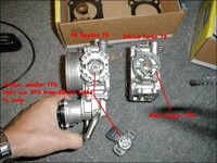
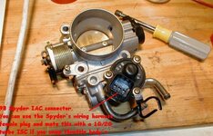
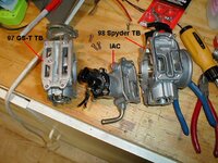
8. turbo model throttle body (92-94 60mm model preferrably)with TPS sensor and ISC. 98/99 Spyder has a smaller TPS that will not work and you must use one that came with turbo TB. Here is a few pics for diffences: 98 TB TPS difference pic1 and 98 TB IAC and 98 TB apart. On the flipside, the wiring plug and connections should work fine on the turbo ISC Idle Speed Controller if you have a SQUARE 6 pin IAC harness connector that looks like the following:
pin1= Green
pin2= red
pin3= gray/black
pin4= green/blue
pin5= red wire
pin6= gray/yellow
*pull the ISC harness and measure the resistance between pins 2 and 5. If they are ~0 Ohms, then you can just plug the the turbo ISC in with no rewiring. 96-97 4G64 Spyders have an inline 6 pin IAC motor which is completely different and will need to be rewired.
9. soldering iron, heat shrink and electrical tape, normal wiring tools and wrenches/sockets plus ohm/voltage meter.
10. Fuel pump 2G rewire mod (not necessary but easier). You can follow this step by step here
11. AMP ECU pins (Large pins: AMP p/n 173631-1 and small pins: AMP p/n 173716-1). Order a few free samples from your favorite electronics distributor like Tyco or DigiKey.
12. 2G knock sensor installed in block and shielded wire ran up to near ECU location. Ground this sensor's shielding
on the metal bracket near ECU and fuel relay module.
Warning: I am not a certified mechanic and don't play one on TV. Follow this procedure at your own risk. If your not proficient at soldering, now's the time to practice. All connections should be soldered and inspected. Don't take shortcuts and each connection should be shiny. Take normal precautions when working with fuel sytem. This is meant as a guideline and I will not assume responsibility for an individual following this procedure.
Procedure for 98-99 Spyder GS! (other years may be close but have different wiring/connectors):
1. Disconnect negative battery post. I wedge something underneath that is non conductive. Unscrew your gas cap also to help relieve pressure. If you have done the fuel pump rewire and have a fuse for your pump near the battery, disconnect it and start the car until it dies from lack of fuel.
2. Pull off both driver and passenger side panels of center console to get at the ECU.
3. Unplug all ECU connectors. The ECU can be removed by 3 10mm screws (2 on driver side bracket, 1 on passenger side).
Pull ECU out and get your turbo ECU.
4. 2G turbo ECU may have a metal case that already has the brackets welded in. Bolt ECU bracket onto stock location.
5. Find your knock sensor wire and ground the shielding on the nearby metal console bracket (see pic below). Locate one small AMP ECU pin ( you ordered those samples didn't you?). You need to connect your signal wire from the knock sensor and carefully strip the end and insert into AMP pin. Crimp the flaps on the AMP pin with a needle nose pliers. I also heated this up and used a tiny bit of solder so it wouldn't come out. Insert this pin into the ECU harness for pin 78. You may need a tweezers to push this all the way in. Look at the other end of the ECU plug to make sure you have it inserted properly. If this is not done correctly, your ECU will not see the base knock signal and you probably won't see over 10 degrees timing.
5A. If you have a 96-97 Spyder, run a new wire and AMP pin into empty ECU harness for pin82 from keyed ignition power (a must!). You can tap the B/W wire off the fuel pump relay located on the passenger side of the console. This ECU pin provides power to the turbo ECU. See the picture labeled fuel pump relay (not module) for this wire.
6. Insert all of the ECU connectors back into your turbo ECU.
7. 98-99 Spyder only: Locate the fuel pump relay module (see above pic). If you have done the fuel pump rewire mod and chassis grounded the pump, you are ready to bypass the Spyder's fuel pump relay module. This extra fuel module is not found on the turbo cars and you already have a fuel pump relay. Look at the 5 wires coming out of this module. They should be:
pin 1: black/red wire
pin 2: white/red wire
pin 3: black/blue wire
pin 4: black/white wire
pin 5: black wire
8. Unplug relay module connector. Cut the wire insulation back about 3 inches on the harness. Cut the wires off pins 1,2, and 3 about an 1.5" from the connector. Tape up the CONNECTOR side wires you cut and plug back into module. Solder the harness side wire from pin1 to pin3 wire (black/red to black/blue). Use heatshrink and electrical tape to insulate. Now cut a black 2 ft piece of custom 18AWG wire that you purchased. Solder one end of this black custom wire to the ECU/HARNESS side white/red wire (not the module connector). Heatshrink or tape connection. Route the other end of this black wire underneath the ECU to the passenger side console panel next to the fuel pump relay. NOTE: If you HAVE NOT done the pump rewire mod on VFAQ.com, cut pin 4 black/white wire and make your own chassis ground to the metal bracket with the harness side wire (you can see pic below with an example of how I grounded my knock sensor).
Remove passenger side console panel. Behind the metal bracket, is the MFI relay and the fuel pump relay. Find/pull your black custom wire out a bit. The relay you want has the following:
pin1= Black/red wire
pin2= black wire
pin3= black/white wire
pin4= black/white wire
The relay can be removed easily without touching the bracket. Use a screw driver to push the relay up and off its slide-mount. Unplug the connector. Cut pin2 black wire an inch back. Solder the black custom wire your routed to the black wire on the fuel pump CONNECTOR. Tape or heatshrink. You can tape up the unused harness side wire that you cut. Plug harness back in the pump relay and remount. See pic below for example.
9. It is time to swap in your 450cc injectors. First decide where you want to mount your resistor pack. I chose a bolt on the firewall near the battery that I could get one 10mm factory screw and washer into the resistor pack top bracket. Your resistor pack probably has one red wire and four other black or colored wires. Temporarily mount the resistor and then measure how much extra wire you will have to run to make it to each injector. Just give yourself extra room and cut yourself four red wires and four black wires well beyond each injector.
10. Unmount the resistor pack and fire up your soldering gun. Crimp and then solder the one red resistor pack wire into one mating 10 AWG spade terminal. Now twist the four red wires you cut and made into the other mating spade terminal connection. Crimp and solder these wires. Plug in the spade terminals and tape or heatshrink over the metal terminal connection.
11. Time for the actual injector signal wires. Solder and heatshrink one black pre-cut wire to each one of the resistor pack black (or non red) wires. See below pic for the harness you are creating.
12. Scary part: Unplug each injector plug. Cut the heat insulation back at least 3 inches on each injector wires.
Cut ONLY the red wire about 1.5" to 2" back from the injector connector. Leave the other injector wire alone.
13. Mount your Resistor pack on the firewall again with your harness. Your homemade harness should have plenty of wire to reach a black and red wire to each injector. I started with the closest injector and cut and spliced one of the red harness wires to the red injector HARNESS side wires. Solder and heatshrink. Make POSITIVE you did not splice the injector connector red wire instead!! Now splice, solder, and heatshrink one black harness wire to the injector CONNECTOR red wire. Triple-check your work as any mistakes will cause the turbo injectors to fail.
14. Follow step 13 for the other three injectors. Again, double-check your work!
15. Once you have the injector harness wired, it's time to make it look factory. Measure and cut off a piece
or corrugated black tubing that you can stuff all of your harness wires into. Stuff the red and black wires
into the tubing and tightly wrap electrical tape around the tubing. Make sure each connection is properly insulated.
16. Now comes the fuel mods. Unbolt the two screws holding the fuel rail. I was able to pull out each injector and replace with the 450cc turbo injector with fuel lines still attached. Make sure that your replacement injectors have a new top O-ring. Re-use the bottom pintle cap rubber cushions from your old injectors if in good shape with no cracks. See diagram below. Verify each injector pops back into the rail snugly. Note that you should put rags under the rail to catch some of extra gas that may trickle out. Once all injectors are in the rail, carefully seat them in the intake manifold. You don't want any leaks!!! Check it again!
17. Torque the fuel rail bolts to 9 ft-lbs. Now plug in your throttle
body IAC connector into the turbo ISC.
18. Make sure your work area is ventilated any spilled gas has evaporated.
Put your gas cap back on and reconnect your battery.
19. Turn the key to 'ON' position and verify the ECU power comes on and check your S-AFC. As a baseline, start your car with -10% on your S-AFC's low and high settings to deal with the Spdyer's higher base fuel pressure (vs 2G Turbo). Start your car and let it idle to relearn it's modified fuel/air. While idling, look at the fuel rail and make positive you don't have any fuel leaks! If so, stop the car immediately and fix the leak. Chances are you don't have an injector seated or forgot the rubber O-ring or pintle bushing.
20. Once your car is idling your in good shape. It may run rich but now you will have hook up your logger and check O2 readings and your fuel trims. I tried to get my STFT around +6% (slightly lean) and my Wide Open Throttle runs around 0.88 O2's. Pay attention while your driving and adjust the SAFC as needed. If you have a logger, make sure your getting around 15-25 degrees of timing during WOT runs. If you only see 10 degrees of timing or less, check your knock sensor wiring for a bad connection.
21. Your DONE!! Congrats and you are now a soldering stud.. Be aware that your engine light may come on due to a lack of a boost and fuel pressure solenoid. This will not affect performance in any way. For emissions testing, Vee hav Vays around this too!
After several messages asking how to do this i decided to repost this guide all credit to Chad Berglund, Although i did tweak and update some steps.
Original Tutorial HERE
Parts list and prerequisites:
1. 95-99 2G turbo ECU. With Studs/Bolts. The N/T bolts are to short.
2. 450cc low impedence injectors from a stock Eclipse turbo car.
3. Turbo Eclipse Resistor pack so you can use the above injectors.
4. Automotive grade 18AWG wire. A roll of red and black works nicely.
5. Corrugated tubing for making a nice wire harness and heat shrink for solder connections.
6. Approximately 10AWG spade terminal connection (male and female).
7. SAFC for tuning and PocketLogger software to monitor. Digital O2 gauge at a minimum. *Note I Reccomend DSMlink instead with a Wideband O2 gauge.
8. turbo model throttle body (92-94 60mm model preferrably)with TPS sensor and ISC. 98/99 Spyder has a smaller TPS that will not work and you must use one that came with turbo TB. Here is a few pics for diffences: 98 TB TPS difference pic1 and 98 TB IAC and 98 TB apart. On the flipside, the wiring plug and connections should work fine on the turbo ISC Idle Speed Controller if you have a SQUARE 6 pin IAC harness connector that looks like the following:
pin1= Green
pin2= red
pin3= gray/black
pin4= green/blue
pin5= red wire
pin6= gray/yellow
*pull the ISC harness and measure the resistance between pins 2 and 5. If they are ~0 Ohms, then you can just plug the the turbo ISC in with no rewiring. 96-97 4G64 Spyders have an inline 6 pin IAC motor which is completely different and will need to be rewired.
9. soldering iron, heat shrink and electrical tape, normal wiring tools and wrenches/sockets plus ohm/voltage meter.
10. Fuel pump 2G rewire mod (not necessary but easier). You can follow this step by step here
11. AMP ECU pins (Large pins: AMP p/n 173631-1 and small pins: AMP p/n 173716-1). Order a few free samples from your favorite electronics distributor like Tyco or DigiKey.
12. 2G knock sensor installed in block and shielded wire ran up to near ECU location. Ground this sensor's shielding
on the metal bracket near ECU and fuel relay module.
Warning: I am not a certified mechanic and don't play one on TV. Follow this procedure at your own risk. If your not proficient at soldering, now's the time to practice. All connections should be soldered and inspected. Don't take shortcuts and each connection should be shiny. Take normal precautions when working with fuel sytem. This is meant as a guideline and I will not assume responsibility for an individual following this procedure.
Procedure for 98-99 Spyder GS! (other years may be close but have different wiring/connectors):
You must be logged in to view this image or video.
1. Disconnect negative battery post. I wedge something underneath that is non conductive. Unscrew your gas cap also to help relieve pressure. If you have done the fuel pump rewire and have a fuse for your pump near the battery, disconnect it and start the car until it dies from lack of fuel.
2. Pull off both driver and passenger side panels of center console to get at the ECU.
3. Unplug all ECU connectors. The ECU can be removed by 3 10mm screws (2 on driver side bracket, 1 on passenger side).
Pull ECU out and get your turbo ECU.
4. 2G turbo ECU may have a metal case that already has the brackets welded in. Bolt ECU bracket onto stock location.
5. Find your knock sensor wire and ground the shielding on the nearby metal console bracket (see pic below). Locate one small AMP ECU pin ( you ordered those samples didn't you?). You need to connect your signal wire from the knock sensor and carefully strip the end and insert into AMP pin. Crimp the flaps on the AMP pin with a needle nose pliers. I also heated this up and used a tiny bit of solder so it wouldn't come out. Insert this pin into the ECU harness for pin 78. You may need a tweezers to push this all the way in. Look at the other end of the ECU plug to make sure you have it inserted properly. If this is not done correctly, your ECU will not see the base knock signal and you probably won't see over 10 degrees timing.
5A. If you have a 96-97 Spyder, run a new wire and AMP pin into empty ECU harness for pin82 from keyed ignition power (a must!). You can tap the B/W wire off the fuel pump relay located on the passenger side of the console. This ECU pin provides power to the turbo ECU. See the picture labeled fuel pump relay (not module) for this wire.
6. Insert all of the ECU connectors back into your turbo ECU.
You must be logged in to view this image or video.
7. 98-99 Spyder only: Locate the fuel pump relay module (see above pic). If you have done the fuel pump rewire mod and chassis grounded the pump, you are ready to bypass the Spyder's fuel pump relay module. This extra fuel module is not found on the turbo cars and you already have a fuel pump relay. Look at the 5 wires coming out of this module. They should be:
pin 1: black/red wire
pin 2: white/red wire
pin 3: black/blue wire
pin 4: black/white wire
pin 5: black wire
8. Unplug relay module connector. Cut the wire insulation back about 3 inches on the harness. Cut the wires off pins 1,2, and 3 about an 1.5" from the connector. Tape up the CONNECTOR side wires you cut and plug back into module. Solder the harness side wire from pin1 to pin3 wire (black/red to black/blue). Use heatshrink and electrical tape to insulate. Now cut a black 2 ft piece of custom 18AWG wire that you purchased. Solder one end of this black custom wire to the ECU/HARNESS side white/red wire (not the module connector). Heatshrink or tape connection. Route the other end of this black wire underneath the ECU to the passenger side console panel next to the fuel pump relay. NOTE: If you HAVE NOT done the pump rewire mod on VFAQ.com, cut pin 4 black/white wire and make your own chassis ground to the metal bracket with the harness side wire (you can see pic below with an example of how I grounded my knock sensor).
You must be logged in to view this image or video.
Remove passenger side console panel. Behind the metal bracket, is the MFI relay and the fuel pump relay. Find/pull your black custom wire out a bit. The relay you want has the following:
pin1= Black/red wire
pin2= black wire
pin3= black/white wire
pin4= black/white wire
The relay can be removed easily without touching the bracket. Use a screw driver to push the relay up and off its slide-mount. Unplug the connector. Cut pin2 black wire an inch back. Solder the black custom wire your routed to the black wire on the fuel pump CONNECTOR. Tape or heatshrink. You can tape up the unused harness side wire that you cut. Plug harness back in the pump relay and remount. See pic below for example.
You must be logged in to view this image or video.
9. It is time to swap in your 450cc injectors. First decide where you want to mount your resistor pack. I chose a bolt on the firewall near the battery that I could get one 10mm factory screw and washer into the resistor pack top bracket. Your resistor pack probably has one red wire and four other black or colored wires. Temporarily mount the resistor and then measure how much extra wire you will have to run to make it to each injector. Just give yourself extra room and cut yourself four red wires and four black wires well beyond each injector.
You must be logged in to view this image or video.
10. Unmount the resistor pack and fire up your soldering gun. Crimp and then solder the one red resistor pack wire into one mating 10 AWG spade terminal. Now twist the four red wires you cut and made into the other mating spade terminal connection. Crimp and solder these wires. Plug in the spade terminals and tape or heatshrink over the metal terminal connection.
11. Time for the actual injector signal wires. Solder and heatshrink one black pre-cut wire to each one of the resistor pack black (or non red) wires. See below pic for the harness you are creating.
You must be logged in to view this image or video.
12. Scary part: Unplug each injector plug. Cut the heat insulation back at least 3 inches on each injector wires.
Cut ONLY the red wire about 1.5" to 2" back from the injector connector. Leave the other injector wire alone.
13. Mount your Resistor pack on the firewall again with your harness. Your homemade harness should have plenty of wire to reach a black and red wire to each injector. I started with the closest injector and cut and spliced one of the red harness wires to the red injector HARNESS side wires. Solder and heatshrink. Make POSITIVE you did not splice the injector connector red wire instead!! Now splice, solder, and heatshrink one black harness wire to the injector CONNECTOR red wire. Triple-check your work as any mistakes will cause the turbo injectors to fail.
14. Follow step 13 for the other three injectors. Again, double-check your work!
15. Once you have the injector harness wired, it's time to make it look factory. Measure and cut off a piece
or corrugated black tubing that you can stuff all of your harness wires into. Stuff the red and black wires
into the tubing and tightly wrap electrical tape around the tubing. Make sure each connection is properly insulated.
You must be logged in to view this image or video.
16. Now comes the fuel mods. Unbolt the two screws holding the fuel rail. I was able to pull out each injector and replace with the 450cc turbo injector with fuel lines still attached. Make sure that your replacement injectors have a new top O-ring. Re-use the bottom pintle cap rubber cushions from your old injectors if in good shape with no cracks. See diagram below. Verify each injector pops back into the rail snugly. Note that you should put rags under the rail to catch some of extra gas that may trickle out. Once all injectors are in the rail, carefully seat them in the intake manifold. You don't want any leaks!!! Check it again!
You must be logged in to view this image or video.
17. Torque the fuel rail bolts to 9 ft-lbs. Now plug in your throttle
body IAC connector into the turbo ISC.
18. Make sure your work area is ventilated any spilled gas has evaporated.
Put your gas cap back on and reconnect your battery.
19. Turn the key to 'ON' position and verify the ECU power comes on and check your S-AFC. As a baseline, start your car with -10% on your S-AFC's low and high settings to deal with the Spdyer's higher base fuel pressure (vs 2G Turbo). Start your car and let it idle to relearn it's modified fuel/air. While idling, look at the fuel rail and make positive you don't have any fuel leaks! If so, stop the car immediately and fix the leak. Chances are you don't have an injector seated or forgot the rubber O-ring or pintle bushing.
20. Once your car is idling your in good shape. It may run rich but now you will have hook up your logger and check O2 readings and your fuel trims. I tried to get my STFT around +6% (slightly lean) and my Wide Open Throttle runs around 0.88 O2's. Pay attention while your driving and adjust the SAFC as needed. If you have a logger, make sure your getting around 15-25 degrees of timing during WOT runs. If you only see 10 degrees of timing or less, check your knock sensor wiring for a bad connection.
21. Your DONE!! Congrats and you are now a soldering stud.. Be aware that your engine light may come on due to a lack of a boost and fuel pressure solenoid. This will not affect performance in any way. For emissions testing, Vee hav Vays around this too!
You must be logged in to view this image or video.
After several messages asking how to do this i decided to repost this guide all credit to Chad Berglund, Although i did tweak and update some steps.
Original Tutorial HERE
Attachments
Last edited by a moderator:
