- Thread starter
- #26
KeelesKustome
15+ Year Contributor
- 882
- 15
- Dec 29, 2007
-
Waverly,
Tennessee
0. no it does not crank
1. voltage at ecu's 82 with key on +12.04
2.ohms to ground from ecu's pin 26 +12.04
3.i did not make it run once, i put a 12 v wire to my 25 pin on the ecu and it activated my fuel pump and turned on my ecu light for 4 second then it went off and it allowed me to loggin with ecmlink and check for any adnomalities and it didn't sho any, but the car was not running.
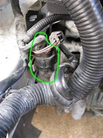
4. i am unsure on the relay pins as what is which... so heres what i got for ya,
the starter relay.
85 87 87
85 30
starting from top left and working down then next single 87 pin, then 87 and 30.
85 has 10.8v when key is on /12.5 when key is turned to start
85 has 10.8v when key is on /12.5 when key is turned to start
single 87 jumps all over the place constantly and when the key/ is turned on it still does but a little lower, voltage was like .005- .078 etc..
87 has .025v when key is on /.015 when tring to crank it
30 has 12.07 and /12.08 when cranking.
heres extra for you i have got so far as i thought you might ask. all at the ecu with it plugged in.
pin 3 fuel pressure solenoid has 11.34 v
pin 8. fuel pump relay has 11.98 v
pin 12. power supply + 0.713 v
pin13. ground has 12.04 v
pin25. power supply +0.713 v
pin 26. ground +12.04 v
pin 36. check engine light +11.89 v
pin 38. MFI relay 7.77 v
pin 71. ignition switch ST -0.001
pin 80. back up power +0.015 v
pin 82. ignition switch 1g +12.04 v
pin 92. sensor ground 12.03 v
i hope i did the important ones, i did this after removing any barrell connectors and solding all wires with shrink wrap over it, it's been a long day at work, while doing this.
tell me what to do next
1. voltage at ecu's 82 with key on +12.04
2.ohms to ground from ecu's pin 26 +12.04
3.i did not make it run once, i put a 12 v wire to my 25 pin on the ecu and it activated my fuel pump and turned on my ecu light for 4 second then it went off and it allowed me to loggin with ecmlink and check for any adnomalities and it didn't sho any, but the car was not running.
4. i am unsure on the relay pins as what is which... so heres what i got for ya,
the starter relay.
85 87 87
85 30
starting from top left and working down then next single 87 pin, then 87 and 30.
85 has 10.8v when key is on /12.5 when key is turned to start
85 has 10.8v when key is on /12.5 when key is turned to start
single 87 jumps all over the place constantly and when the key/ is turned on it still does but a little lower, voltage was like .005- .078 etc..
87 has .025v when key is on /.015 when tring to crank it
30 has 12.07 and /12.08 when cranking.
heres extra for you i have got so far as i thought you might ask. all at the ecu with it plugged in.
pin 3 fuel pressure solenoid has 11.34 v
pin 8. fuel pump relay has 11.98 v
pin 12. power supply + 0.713 v
pin13. ground has 12.04 v
pin25. power supply +0.713 v
pin 26. ground +12.04 v
pin 36. check engine light +11.89 v
pin 38. MFI relay 7.77 v
pin 71. ignition switch ST -0.001
pin 80. back up power +0.015 v
pin 82. ignition switch 1g +12.04 v
pin 92. sensor ground 12.03 v
i hope i did the important ones, i did this after removing any barrell connectors and solding all wires with shrink wrap over it, it's been a long day at work, while doing this.
tell me what to do next


 .
.