The Top DSM Community on the Web

For 1990-1999 Mitsubishi Eclipse, Eagle Talon, Plymouth Laser, and Galant VR-4 Owners. Log in to remove most ads.

Please Support STM Tuned
Please Support Rix Racing

Wife's 2GA Talon Restoration and Build (140s or bust)

This site may earn a commission from merchant
affiliate links, including eBay, Amazon, and others.

This site may earn a commission from merchant affiliate links, including eBay, Amazon, and others.

wishihadatalon

20+ Year Contributor
2,615
72
Aug 18, 2002
Grand Rapids, Michigan
Hi guys, I don't typically post too much about my cars but I've lately been lacking motivation to keep going on the project.

The background for this car is as follows. This car is the first car that my wife purchased on her own. At the time (2004) we were dating and I had a pretty clean 1GA Talon. We set out to find a black 2GA Talon TSI AWD 5spd and we were able to find one in town. The car was bone stock (returned to stock by previous owners) and didn't have any visible rust, the only negative was a very disgusting set of chrome wheels.

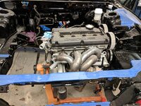
After a few years of daily driving in Michigan the car the stock 7 bolt crank walked and the strut towers started showing signs of dreaded strut tower rust. We did a stock 6 bolt rebuild on the car, added a 16g, fp exhaust manifold, megasquirt ecu, supporting fuel mods, and a slight clutch upgrade. On this setup, the car managed a 12.1 at 114mph with a stock side mount intercooler.

Here is a photo of the setup slightly unfinished.
41.JPG


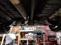
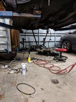
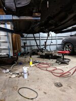
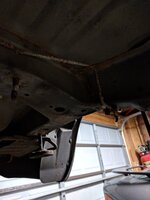
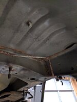
At some point during the daily years, we had a "shop" repair the strut tower rust. When we received the car back, I could tell it wasn't quite right, but we lived with it. As the years went on, we upgraded the turbo charger to an HX40 and I designed and built a front mount that fit between the factory 2GA fog lights. While doing all of this, the tower rust returned. After trapping 101mph in the 1/8 @3300lbs with the stock motor, finding the limits of the Centerforce dual friction clutch, and poking a hole in the strut towers, I decided it was time to tear it down.

Here are the last pictures I have of it
40.JPG

42.JPG
 
On to the tear down. I've never done any body work, but I know people who have and I've watched enough power block to understand the basics. I say this as confidently as I felt, before I understood the learning curve involved.

Initially what I found. Terrible bondo job plus crappy patch job.
1.jpg


After stripping the towers down. You can see the hole on the drivers side strut tower.
36.jpg


Then I started digging into it.
2.jpg
3.jpg
7.jpg


Once I had all of the cancer cut out I started stripping down a decent set of towers I got off of a parts car that a buddy gave to me. Stripping these towers down was a great exercise in understanding the construction of the factory sheet metal and also why they tend to rust so much. Unfortunately I only have one picture of these.
37.jpg
 
One the spare set of towers were deconstructed, I began cutting out patch panels to fix the bad spots and began welding them in.
5.jpg

8.jpg


Somewhere along the way I decided that my garage did not have the appropriate tools needed to handle the scope of project I was taking on. I decided to move my car to my coworkers house to speed up progress. Sad dsm on a trailer, nothing new there.
38.jpg
 
Once at my coworkers house, real progress started to happen. I sandblasted the whole engine bay to expose any areas that I wasn't able to see under the paint. This picture was a bit after blasting, and you can see a little bit more cut out of the strut towers than before.
9.jpg


Once able to see what I was working with, I started cutting out patch panels from my set of donor towers.
10.jpg
11.jpg
12.jpg


Once everything was fitted, it was time for welding in. All panels were sand blasted, prepped, and sprayed with SEM weld through primer prior to welding. On that note, weld through primer makes welding an absolute bi***!
13.jpg
14.jpg
15.jpg
16.jpg
17.jpg
18.jpg
19.jpg
20.jpg
 
With the welding and blending complete on the towers, it was time to finally prep the car for primer. We covered the whole car in 6mil plastic and taped off all areas to prevent over spray. BTW I really hate doing tape work. Seems like such a simple task, but it's horribly time consuming and not at all rewarding.
21.jpg


Finally after many hours of hard work, it's finally ready for primer!!! I decided to use Southern Polyurethane products for this because I read a many good things about them online and had a few recommendations. I highly recommend their products.
23.jpg

22.jpg


The finished primed product. This felt like a huge milestone once we were done.
25.jpg
 
With the epoxy primer set and all of the bare metal now sealed in to prevent future rust, we set out to clean up the imperfections.

Small amounts of bondo and puddy coat were used to clean everything up and make it smooth.
26.jpg


Once done, we applied another coat of the epoxy primer (not pictured) and then applied a coat of build primer.
28.jpg
29.jpg
30.jpg


The build primer was wet sanded down in high visibility areas to have a nice smooth surface after paint is applied. We also used 3M seam sealer to stop moisture from getting between the layers again.
31.jpg
32.jpg


During this time, I also set out to get the carbon fiber hood fitted and get the Aerocatch hood pins installed. The hood will be primed, sanded, filled, primed, and painted to match the car. I'm not a huge fan of exposed carbon fiber so finding a $50 blemish hood was largely beneficial to me.
27.jpg
 
This whole process took around 8 months to complete. I'm a manufacturing engineer in the automotive field and am currently working on a fairly large launch that required quite a bit of travel from me. So between the travel and the 1/2 hr drives each way to work on the car, the time line was stretched pretty far. While on one of my work trips, my coworker completed the painting.
33.jpg


Same picture but 8 months later!
39.jpg


And this brings us to today. Now with it home, I can start finishing up some of the details of the rust repair. This is 3M 08881 undercoating sprayed in areas where rocks and debris can hit.
34.jpg
35.jpg


On my next posts, I'll show some of the breather work I have been working on and also an electric power steering solution I am working on to clean up the engine bay and remove the entire hydraulic system.
 
Well done! When it's complete, body work is satisfying, but can't help the feeling of frustration of the hours needed just to return our cars to the way they should already be. It's especially madenning when you discover how poor design played a part in hidden areas that turn into problems later. Great photo documentation. Congratulations on a great job and thanks for sharing this with us.
 
Thanks for the kind words guys. I didn't really do too much on the car today, my hammock was way more appealing. I did however make it to the junk yard for the Memorial day sale to try and get my COP coils on sale. After an exhausting search through the import section and seeing every single Toyota picked through for it's coils, my wife found one car with the engine cover still on it. Upon removal of the engine cover, I was able to get the Denso coils that I was looking for.

IMG_20170527_234646.jpg


These are used typically in the Evo world and in the SpoolinUp COP system. It is my understanding that these will not typically work on a dsm because we have an external ignitor where the Evo has the ignitor circuit built into the ECU. Please correct me if I'm wrong on this. Either way, my solution for this will be farther down in this post.

Also last night I was able to assemble the shifter base. The shifter arm itself has been shortened by 2" using a jig I designed and had built by a friend. Using my jig, I can shorten directly along the vertical axis and prevent any distortion or bad assembly. You can also see that the whole assembly has been powder coated. This is just a small part of a large pile of parts that have been powder coated by a local guy. More picture of that later.
IMG_20170527_234450.jpg

IMG_20170527_234607.jpg


If you're wondering about cornbread, my buddies think I'm country I guess, so they call me cornbread.

Now onto the solution for the COP and certainly my biggest purchase ever for a DSM. A huge thanks to Tyler at Force Engineering for helping me select this. His advice, support, products, and services have helped my car perform at its best and flawlessly over the last few years. If you're looking for things that work, he's your guy.

IMG_20170527_235334.jpg

Pictured is an Elite 1000 Ecu with wideband controller, 2x pressure sensors (fuel and oil), coolant temp sensor, flex fuel sensor, and EBCS. I've have very little time over the last few weeks to look at the documentation for this or to look at the software, but I'm very excited to learn something other than Link or the Megasquirt systems I have been using for the last 12yrs.

That's all for tonight. Thanks for looking.
 
Last edited:
So I haven't updated in a bit. I've been chipping away bit by bit on the car but it's hard to make a huge push because I still need to get a few things painted and powder coated.

This weekend I dropped off my #41 brake booster, proportioning valve, and the steering box housing off to a friend for paint. These items are getting painted the same color as the engine bay. I also worked on a mounting solution for the Haltech ecu and wideband controller. The bracket that I used for mounting is the transmission computer bracket from an auto car. The car I got the strut towers from was an auto car and I ended up finding this bracket and saved it for this specific purpose. If I ever have to service the ecu, it will be a total pain, but during normal operation this is a nice packaging solution that will keep the ecu out of the way.
IMG_20170530_221327.jpg
IMG_20170529_224402.jpg
IMG_20170530_220730.jpg
IMG_20170530_220806.jpg

Here is where it will sit. Tucked up nice and tight.
IMG_20170530_222122.jpg
IMG_20170530_222154.jpg


I've basically got my coil-on-plug setup done. I designed the plate in CAD and then printed to scale at work on paper to verify fitment. Also you can kinda see my -12 breather setup that I designed, had machined, welded and blended into the factory valve cover. I plugged the original breather and PCV holes for a very clean look.
IMG_20170530_225400.jpg


For the breather setup, I've been given a lot of crap for this on the Facebook groups. My plan was originally to run two -12 fittings to a vented catch can but after discussing with a few people, I decided to also vent the bottom end to help with any oil drain back problems that might arise from all of the crank case pressure coming up through the oil drain back channels. BTW, I know how this forum feels about vented catch cans, but after many conversations with high hp drag racers, I'm comfortable saying that this is the best possible way to go short of an exhaust driven solution. If someone can provide me with crank case pressure pressure data from a car with a 60mm+ size turbo at 40-50psi that has a turbo driven crank case evacuation system that looks favorable, I'll consider changing.
IMG_20170527_235507.jpg

I made a fitting for the back of the block. It was really nerving to drill such a big hole in the back of the block. The hole is tapped for the same thread as the DSM axles.
IMG_20170527_234802.jpg

The final breather location is the stock balance shaft location on the front of the motor. I designed and machined a fitting that uses an o-ring to seat against the stock shaft seal ledge. The flange was then designed to work with the Kiggly Racing 12 tooth crank trigger setup. Overall I'm super pleased with how this turned out.
IMG_20170527_234750.jpg


My final update is one that I've been working on for almost a year now. After looking into the MR2 or Renault electric power steering pumps, I decided I wanted to look for an alternative. Looking around online, I saw vintage car people doing an EPAS setup on their cars. I decided to pull a steering column from a Chevy HHR and start retro fitting the electric assist motor to the car. Making this fit isn't really easy because the motor is pretty bulky, but it can be done while allowing plenty of room for your feet under (I wear a size 12 shoe and have plenty of room). I bought a very simple controller from epowersteering.com which has a manual potentiometer to manually adjust assist. The whole system will be started using the manual potentiometer which will need to be adjusted from parking lot to highway driving, but I have most of the code written for an Arduino digital potentiometer solution that works based off of VSS feedback. If the setup works as well as I hope, I'll get the Arduino setup going later this year.

As you can see, I had to make a flange to bolt to the Chevy steering motor. I then cut down and welded the stock steering tunnel to the flange.
IMG_20170604_214529.jpg

IMG_20170604_214618.jpg


I ended up getting really lucky and discovered that the outlet on the Chevy motor was the same size and spline count as the stock firewall pass through shaft.
IMG_20170604_214631.jpg


Here it is installed. I did all the test fitting on a car that I ended up scrapping. It fits around the stock brake pedal assembly and clutch assembly without any issue.
IMG_20170604_220158.jpg

IMG_20170604_220140.jpg
IMG_20170604_220135.jpg


That's all I have for right now, hope you enjoyed reading.
 

Attachments

  • IMG_20170604_214719.jpg
    IMG_20170604_214719.jpg
    300.6 KB · Views: 86
My final update is one that I've been working on for almost a year now. After looking into the MR2 or Renault electric power steering pumps, I decided I wanted to look for an alternative. Looking around online, I saw vintage car people doing an EPAS setup on their cars. I decided to pull a steering column from a Chevy HHR and start retro fitting the electric assist motor to the car. Making this fit isn't really easy because the motor is pretty bulky, but it can be done while allowing plenty of room for your feet under (I wear a size 12 shoe and have plenty of room). I bought a very simple controller from epowersteering.com which has a manual potentiometer to manually adjust assist. The whole system will be started using the manual potentiometer which will need to be adjusted from parking lot to highway driving, but I have most of the code written for an Arduino digital potentiometer solution that works based off of VSS feedback. If the setup works as well as I hope, I'll get the Arduino setup going later this year.

As you can see, I had to make a flange to bolt to the Chevy steering motor. I then cut down and welded the stock steering tunnel to
I ended up getting really lucky and discovered that the outlet on the Chevy motor was the same size and spline count as the stock firewall pass through shaft.

That's all I have for right now, hope you enjoyed reading.

Darn You! I have the hard parts made and the same manual controller, just haven't gotten around to finalizing and installing it, but literally the exact same epas setup will be going in my car haha. Good deal tho, you'll have to let me know how it works once you get it on the road again.

Great build otherwise, keep it up!
 
For sure man, let me know if you have any questions. I did forget one picture in the last post. I had to do major surgery on the shaft to make it work. Sectioned the HHR shaft and the stock DSM shaft and had to do a little bit of machining to make it all work. Stock collapsible shaft on the top and the modified one on the bottom. I should note that this still has some ability to collapse.
IMG_20170604_214719.jpg
 
I actually did the exact same thing with mine haha, great minds think alike? Mine isn't finish welded yet, but it's the exact same concept, I just need to align things a tad and test fit. I actually left my support tube a bit long to extend my wheel toward me cuz I'm a tall bastard.

I would be interested in your arduino setup when you're finished with it, I wanted to setup a speed sensitive system, just hasn't found the diagrams for the motor yet (i.e.- lazy), but yea I'll keep an eye on this and let you know of I finish mine. :thumb:
 
That's some nice work. I had not even thought of upgrading to EPAS.
 
I actually did the exact same thing with mine haha, great minds think alike? Mine isn't finish welded yet, but it's the exact same concept, I just need to align things a tad and test fit. I actually left my support tube a bit long to extend my wheel toward me cuz I'm a tall bastard.

I would be interested in your arduino setup when you're finished with it, I wanted to setup a speed sensitive system, just hasn't found the diagrams for the motor yet (i.e.- lazy), but yea I'll keep an eye on this and let you know of I finish mine.
thumbsup.gif

I'm going to cheat a bit because I too don't know exactly how the motor is controlled via the epowersteering kit. I'll just put the arduino output in place of the epowersteering 100k ohm manual potentiometer and should be good to go. I'll let you know when I finally get it done. It's been almost 10yrs since I've written any code and I'm figuring out the learning curve is much more difficult as I get older.
 
I'm going to cheat a bit because I too don't know exactly how the motor is controlled via the epowersteering kit. I'll just put the arduino output in place of the epowersteering 100k ohm manual potentiometer and should be good to go. I'll let you know when I finally get it done. It's been almost 10yrs since I've written any code and I'm figuring out the learning curve is much more difficult as I get older.

It'll prolly work fine. I recall seeing a vid on YouTube from a guy in the UK stating that the signals the motor controller gets are vehicle and engine speed. If that's the case it's be easy to get the signals.

If i find the specs and diagrams I'll post them up here.
 
I realized today that I haven't updated in quite a while. I don't have too many big progress updates, but I have been gathering more parts. One benefit of living where I do, is that I'm 45 minutes away from TRE. I picked my transmission up sometime last year, but after pestering Jon for a few months, I was able to convince him to sell me his final Evo 3 5th gear set. So earlier this year, I dropped off my pretty unused Stage 3 transmission to him and had him install the new gear set. So two weeks ago I went and picked It up.

For the drivetrain at this stage of the build, I have a the stage 3 transmission, rebuilt transfer case, ACT flywheel, and a Southbend SSX full face clutch.
IMG_20170616_232405.jpg
IMG_20170616_232523.jpg
IMG_20170616_232623.jpg
IMG_20170616_232627.jpg
IMG_20170616_232752.jpg


I was also able to install the Hella horns that I purchased last year. I'm hoping these will work well. I told Jon I wouldn't launch the car too much with his transmission, so I have to be able to do some rolls.
IMG_20170616_231830.jpg


Today I was able to mount the remote filter housing. I had to do this for a few reasons. First reason is clearance. Two years ago I was preparing for MOD and found some metal in the oil filter. After replacing bearings and doing a full fluid change, I got it all buttoned up and ready to go. Well when I pulled the oil filter, I had to drop the down pipe to get the filter off. The down pipe had slotted holes and when I put it together, it was all the way to one side. A couple hours from home I noticed my oil pressure dropping. Needless to say, the down pipe rubbed a hole into the filter and it was leaking oil. After looking at alternatives, I thought a forward facing filter housing would work, but the filter would interfere with my hot side intercooler pipe. So this is my solution. Not a new idea, but I really like the idea. I get an extra quart of oil capacity and the sandwich adapter has pretty nice cooling fins.
19496506_1506505946038410_848794742_o (1).jpg

19495624_1506506019371736_859267970_o.jpg
IMG_20170626_000746.jpg


Also, the remote housing is mounted to the frame rail using rivnuts. If you've never used these, you need to look into them. They are excellent at giving you a great mounting location where there wasn't one.
IMG_20170626_000728.jpg

And finally, I hit a snag with my crank case evacuation setup. Unfortunately the 180 degree swivel fitting has too big of a profile and interferes with the accessory belt. I'm planning on running a Saturn alternator with a Jay Racing relocation kit. I could use the inside belt locations that were originally meant for power steering and air conditioning, but after measuring the pulleys, the water pump would be over driven by 67% which I think would cause cavitation and a reduction in cooling efficiency. I'm going to contact Summit Racing tomorrow and see if there is a smaller profile 180 fitting or if I'll need to run a compact 90 and plan new routing for the hose.
19496465_1506501416038863_1426391568_o.jpg


Thanks for looking!
 
It isn't thermostatic. I went back and forth on whether I should run a cooler or not. Ultimately I decided not to given the greater oil capacity, cooling find on the sandwich adapter, and remote location for the filter. If I drove the car harder or did road racing, it'd be a no brainier.
 
Wow, it's been quite a while since I have updated this. I unfortunately haven't made too much progress on the car, but I am chipping away. Since my last update, I have acquired a very important tool and got it all setup. After seeing it on a Facebook ad, I was able to pick up a Rotary 2 post asymmetrical lift. When finally getting around to installing, I found out that I had to have a thicker floor. So I set it up where I wanted it, marked the floor and cut it out. I ended up digging down 12" (2.5x more than recommended) and using a high compressive strength concrete.

Here is the car finally up on the lift and my buddies sweet 98Tsi AWD coming in out of the elements.
IMG_20180113_111550.jpg


So with the car finally off the ground, I started tearing into it. I've planned on going with 1/2" fuel feed and 3/8" return lines, but I am absolutely not a fan of braided soft line from the tank to the engine bay. So after I was pulling the factory lines, I found that the rear brake lines were a little sketchy. With that discovery plus trying to figure out my fuel system, I decided to pull the fuel tank and the rear end. Once out, the brake line rot was worse than anticipated. So now, I'm using my 3d printer to create a tubing straightener so I can buy a coil of 3/16" tubing and redo the brake lines.
IMG_20180122_222711.jpg
IMG_20180122_222721.jpg
IMG_20180122_222728.jpg


As stated previously, I have a 3d printer. I purchased it to prototype parts, create little odd items for the car, and my wife does quite a bit of cosplay. After spending a bit of time under the car and knowing my eventual fuel line sizes, I came up with a solution to route the lines properly.
IMG_20180120_225320.jpg

Factory on the right and the new on the left.
IMG_20180120_225736.jpg

And finally, my in-laws gave me a really nice Imperial tubing bender for doing small lines for Christmas. One thing I've always wanted to do is a hard oil feed line for my turbo. Once I purchased a relatively expensive stainless steel street tee, I was able to get this line done. The tee allows me to keep a factory sender so I don't have to run an aftermarket oil pressure gage (I'll set up the fail safes in the Haltech to protect the motor).
IMG_20180119_205752.jpg
IMG_20180119_205801.jpg
IMG_20180119_205805.jpg
 

Attachments

  • IMG_20180110_220728.jpg
    IMG_20180110_220728.jpg
    347.8 KB · Views: 100
  • IMG_20180120_125240.jpg
    IMG_20180120_125240.jpg
    378.9 KB · Views: 98
  • IMG_20180122_001721.jpg
    IMG_20180122_001721.jpg
    340.1 KB · Views: 101
  • IMG_20180122_001737.jpg
    IMG_20180122_001737.jpg
    275 KB · Views: 107
  • IMG_20180122_222700.jpg
    IMG_20180122_222700.jpg
    220.4 KB · Views: 99
  • IMG_20180122_222703.jpg
    IMG_20180122_222703.jpg
    240.3 KB · Views: 103
Support Vendors who Support the DSM Community
Boosted Fabrication ECM Tuning ExtremePSI Fuel Injector Clinic Innovation Products Jacks Transmissions JNZ Tuning Kiggly Racing Morrison Fabrications MyMitsubishiStore.com RixRacing RockAuto RTM Racing STM Tuned

Latest posts

Build Thread Updates

Vendor Updates

Latest Classifieds

Back
Top