The Top DSM Community on the Web

For 1990-1999 Mitsubishi Eclipse, Eagle Talon, Plymouth Laser, and Galant VR-4 Owners. Log in to remove most ads.

Please Support ExtremePSI
Please Support STM Tuned

1G TCU capacitor failure URGENT

This site may earn a commission from merchant
affiliate links, including eBay, Amazon, and others.

This site may earn a commission from merchant affiliate links, including eBay, Amazon, and others.

o0GuitarKid0o

Proven Member
1,069
163
Dec 12, 2013
Winnipeg ,MB, MB_Canada
1991 laser with f4a33 turbo automatic transmission
TCU=Md750093 (eprom)
Eprom chip=m674
Alright dont want to jump the gun here
But would like a second opinon on the capacitors traces

Litteraly my car out of no where went into limp mode so i went to go check the codes with my palm logger with mmcd-TCU but i got a serial com error

A/t fuses wasnt blown so i new it was my tcu causeing the issues since this transmissions been rebuilt 2 times in the last 7 years and was mechanicaly strong a few days ago i no its not a mechanical issue

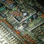
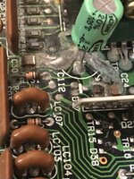
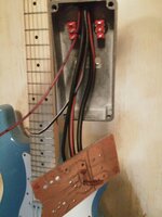
I removed the capacitor to find this (pic 1)

So i cleaned er up and soldered a new 47 uf cap in and then i noticed the trace looks like its gone??
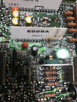
Anyone have any pictures of what the traces are suppose to look like?

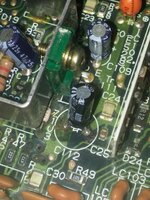
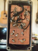
It seems to me the only the POSITIVE side of the cap (c112)is affected since i still have a connection on the negitive trace of the capacitor(c112) from R48 and R48 - c24 is connected although it could use a touch up im leaveing those traces alone for now

Now it looks to me like the (c112) is suppose to connect to the to the third pin of (ic 102) whitch is that white board to the right of (c112)
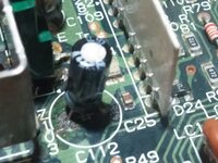
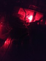
LOOK AT PIC 2 and 3

Anyone have a picture or a tcu kicking around with a clear view of whats under (c112)

Anything helps guys thanks
 

Attachments

  • 20170213_011602-1500x1500.jpg
    20170213_011602-1500x1500.jpg
    521.6 KB · Views: 248
  • 20170213_174033-1200x1600.jpg
    20170213_174033-1200x1600.jpg
    337.2 KB · Views: 280
  • 20170213_184737-1600x1200.jpg
    20170213_184737-1600x1200.jpg
    215.2 KB · Views: 246
I have a 92 diamante tcu that has been repaired in the same spot that is dead. Same car 91 laser fwd turbo. I gave up on trying to find a good 3 prong tcu. I wired in a 99 gst tcu and have no ill effects from it.
 
I have a 92 diamante tcu that has been repaired in the same spot that is dead. Same car 91 laser fwd turbo. I gave up on trying to find a good 3 prong tcu. I wired in a 99 gst tcu and have no ill effects from it.
Really ? How much of a pain was it? I wouldnt mind doing that at all
I need a tcu i know for a fact
 
After checking the 2 pin outs from a 3 plug to a 2 plug tcu
Every pins the same just orientated différent on the connector. Why Mitsubishi would make a new tcu with the same exact pins for a 92 beats me..
Worst case ontario i can opt in for a 92 ecu and connectors

Wish i could somehow get my hands on the schematics for the tcu
 
I'm looking for one from after I removed the 47uF capacitor but it looks like I'll have to see if I still have one of those TCU's in the basement and get a picture.

You must be logged in to view this image or video.


Notice how the copper pads at the end of the traces are still copper colored vs yours which are brown and crusty. That's all corrosion that needs to be fixed. Same of the non-shiny solder.
 
So those holes are there to transfer one side of the pcb to the other ?
My boards in good shape everywhere else As far as the eye can see atleast

Now is there any way you know if the positive side of the bad cap c112 is connected to the third pin on IC102?
If i can use a jumper wire on the back of the pcb instead of trying to jump solder on the copper trace it would be better

Noticed C114 is corroded on the pads and CA2 and CA1 have corrosion under them

I have 5 ecus so im sure i can use one to salvage parts from

My tcu gives me no voltage on the diagnoises port but i get voltage to the connector


This Makes me wanna make my own schematics with a good tcu.
Mitsubishi aint gonna release the schematics
Anytime soon

I'm looking for one from after I removed the 47uF capacitor but it looks like I'll have to see if I still have one of those TCU's in the basement and get a picture.

You must be logged in to view this image or video.


Notice how the copper pads at the end of the traces are still copper colored vs yours which are brown and crusty. That's all corrosion that needs to be fixed. Same of the non-shiny solder.
 
Sorry about not getting back sooner. My work hours are horrid.
Anywho, I had grabbed a 99 tcu from a clean low mileage car at pull a part. Have no idea why I have never owned a 2g. Started going through diagrams and only saw small differences wiring wise. Tcc solenoid and temp sensor wiring was some things I ran into with this. After wiring in the first time I left the tcc wire disconnected. Went a couple days with that fault code then went into limp mode. Went back to the 99gst grabbed the tcc solenoid. Wired it in at the tcu and grounded to the appropriate sensor ground for it and it hasn't thrown a code since. The info on this swap was and is almost non existent. I had spent days trying to find anything to help but in the end I used three wiring diagrams. 1g 3plug turbo non tcc solenoid. 1g 2plug turbo tcc solenoid. 2g turbo. The economy power switch is non functional for this but I do recall having to wire into it somehow. I will try and get a diagram wrote up on what I did to make this work for me and the tcu part number I used from the 99. It may take a lil bit because i depinned the tcu harness so I could still go back to a 3 plug if I ever had a need to.
That would be awesome regardless if i end up doing that . us 1g auto guys dont have many options for a different tcu from factory


Now i looked at the 2 plug tcu pinout vs the 3 plug and litteraly found no differences other than the layout of each wire
I thought the tcc was only in non turbos? Im proberly wrong on that one but remeber seeing something in my fsm


So dug into my tcu today fixed 2 bad traces and replaced that 47 uf capacitor again since i have a few lyeing around from electronics in high school
(should of been done last year when i pulled the tcu my dumb !)

Lets hope for the best its a pain in the ars to solder new connections in ill tell you what

I removed the heat sink for better accesability
 
The 92 diamante tcu that I have had been repaired by someone, who knows but the seal had not been broken until I did.
I took a few photos to show the same damage and repair that had been done to this. Some things are not the same on these but are very similar.
 

Attachments

  • IMG_1786.JPG
    IMG_1786.JPG
    331.5 KB · Views: 119
You must be logged in to view this image or video.
The 92 diamante tcu that I have had been repaired by someone, who knows but the seal had not been broken until I did.
I took a few photos to show the same damage and repair that had been done to this. Some things are not the same on these but are very similar.
Yeah i noticed ic102 is writtin in a different direction
Do you have a clearer picture? Im guessing thats solder on the traces?

Heres a few pictures of my repair i did i still have no heartbeat tho

Im gonna replace some capacitors if the part numbers match

Im wondering tho my 101 disk capacitor (c114) looks shot cant get any nf or uf readings with my DVM so im guessing any 101 disk capcitor will do (i have a bunch ) also my (c101) and (c102)have some residue under them.
Hopefully one of my spare ecus have two 7 pin capacitors with the same part number as the one in my tcu

Any one no the best way to test the transistor thats green (TR111)

Just wish i had schematics it would be so much easier

Oh and r48 is not connected to that patch i did i made sure of it
 
I bought abunch of capacitors and a ZENER diode but i have no clue if its even the right one (2nd pic) its the diode under the transisters heat sink beside (R118)

I have spare 101 capacitors .0001 uf or .1nf
Because one of mine are a little corrorded


This is a little better you can see most of the topside ground trace for C112 and the repaired via's above R48.

You must be logged in to view this image or video.


Hmm im guessing i should disolve the protective layer and do the same thing
Looks like somthing i can handle


Im also makeing an shift box so i can drive it normaly
Id love to hook up a display for gears but it would take me some time to figure out
I bet i have everything i need
The metal project box fits my hand nicely

Im gonna wire the 2 toggle switches with a 12v wire on the middle pin of each toggle switch (common)

Basically its an on on switch that has a 12v source
 

Attachments

  • 20170216_184137-2080x1560.jpg
    20170216_184137-2080x1560.jpg
    465.6 KB · Views: 93
  • 20170216_184148-2080x1560.jpg
    20170216_184148-2080x1560.jpg
    366.2 KB · Views: 88
That's pretty slick. When I bought mine it had no tcu period. I did the kiggly shift mod wired mine up so it was 1 2 D, and od button was 4. Fluid stayed a lot better looking than I thought it would have.
 
That's pretty slick. When I bought mine it had no tcu period. I did the kiggly shift mod wired mine up so it was 1 2 D, and od button was 4. Fluid stayed a lot better looking than I thought it would have.

Dam i wanna do that now LOL it would be easy because the inhibiter switch is really close to the solenoids

Do you remeber how you wired it?
 
I grabbed a spare inhibitor that I used off the 92 diamante. So I wouldn't have to chop mine up. I have it in the garage and I'll post how I did it when I go to see how I did the tcu. Work is killing me
Cool man thanks

I know 1st is A on,B on
2nd A off, B on
3rd A off, B off
4th A on, B off

Just seems tricky to do with the inhibitor switch , but it seems safer in my opinion to do it like that

Gotta figure out down shifting any tips?
 
You must be logged in to view this image or video.
Got my circuit designed for my new shift box.
This is V-0.98
Its not finnished yet because i have to move the power connetions down for a cleaner install

Eventually wanna do shift protection and a gear display

Just gotta find a chip for my needs

I would of bought a roadsurge box but havent recived a message from him since last year
 
ForcedFour??? His unit works great in my sons Talon with a display and up/down buttons. He builds them all.
 
You must be logged in to view this image or video.

V-1.0
ForcedFour??? His unit works great in my sons Talon with a display and up/down buttons. He builds them all.
Ill have to check it out forgot about them!


For now im gonna have to use my new toggle switch remote, i added a easy disconnect connector also.
The Schematic i made is at the top of this post.
R1=1.1k ohm resister. J1= jumper wire 1
R2=1.1k ohm resister. J2= jumper wire 2
Sa= solenoid A. S1= toggle switch 1
Sb= solenoid b. S2= toggle switch 2
-/+L1= led 1. -/+ L2=led 2
Gnd= ground. Nc= no connection
+= power (im running 2 seperate 12v lines to each solenoid)

But yeah tell me.what you think , i dont have ammonium persulfate so i had to etch the board with a ofla knife .
Also had to add jumpers to the toggle switchs due to me running the solenoid wires on the wrong part of the switch on the pcb
I corrected it in the schematic

Each red Led lets me know theres power going to the pcb on each side

Im gonna start focusing back on my tcu tonight will see what happens.
 

Attachments

  • 20170218_003305-1560x2080.jpg
    20170218_003305-1560x2080.jpg
    229.1 KB · Views: 83
  • 20170218_040244-1560x2080.jpg
    20170218_040244-1560x2080.jpg
    191.4 KB · Views: 98
  • 20170218_161902-1560x2080.jpg
    20170218_161902-1560x2080.jpg
    218.6 KB · Views: 87
  • 20170218_053236-1560x2080.jpg
    20170218_053236-1560x2080.jpg
    136.3 KB · Views: 81
Last edited:
You must be logged in to view this image or video.
She works good for under 15$
Can anyone chime in about shifting? More down shifting than up
 
I said I'd get back with how I wired in a 2g tcu into my 91 laser. I wrote it and took some pictures.

Like I previously said (I think I did) pin 1 on the 2g tcu is for the tcc solenoid. I took a tcc solenoid and wired it straight to the tcu, jammed it in dash with tcu.

Only reason for that was after a couple days of driving with a fault code for tcc solenoid. It would go into limp mode. Thought why not just hook it up, hasn't came back for me since. I had to grab the tcc solenoid out of the car I got the tcu from.

This may get flamed and hated on but it has worked for me almost a year now.

You must be logged in to view this image or video.
 
Update:
So i got my new (chipped tcu) thanks to a member on here and im loving it !

In the end my og tcu was cooked due to leaky capacitors .
I will update this thread when i find time to look for new "Capacitor Arrays" part number B8xc0114 and a 11 in the bottom corner
Can only find B8xC0117 arrays.
i have no idea if the part numbers have changed in 26 years
Also ill do my best to add as many part numbers that i can when i have free time .

Ill add a link to the tread when the time comes, us Auto guys dont have much information to go on so doing my part! Especialy tcu repair!

I have a total of 4 spare ecus and now a spare broken tcu so i could salvage parts from one .

Also i will make a schematic for around the bad capacitor that leaks around that green transistor for DIY'ers
I had a hell of a time tracing it out from pictures

The chips cool

"Economy" is nice smooth shifting but more aggressive than stock

"Power" will shit to redline and be 100% full line pressure, im not letting it because if you lower your TPS input it will shift when ever you want.
my valve train just has a stock rebuild on it so 6k is enough for now LOL


Homemade shift box awnsers:

Before i forget when shifting the more load you put the smoother it shifts . also try and shift like an auto not like a manual.
When your driving in rush hour you need to shift quickly i found
1st--20 km/hr or 1500 rpm
2nd--30 km/hr or 2000 rpm
3rd--50 km/hr or 2500 rpm
4th-- 60 km/hr or 2500 rpm
Will call this economy .
NOTE: stay on the gas dont lift off your foot at all when shifting and be ready to use those breaks!
half the time you gotta stop anyways LOL

Now will call this power mode
Keep it under full throttle the entire time and shift at any rpm you want it over 3500 rpm it will shift harder if you let off the gas and shift (trust me).
Also watch your speed its very easy to get carried away.
I got pulled over but the cop was awesome and told me to just slow down but not before asking what that contraption i had was hah (shift box)

Down shifting i found when your off the throttle
4th -3rd at 1800 rpm is very smooth
3rd -2nd 1200 rpm is smooth
2nd-1st id say anything at idle rpm and under 5 km/hr or stopped

If it clunks than down shift at 1200 rpm on all gears while on the brake

Noticed you can acually go from 4th to secound under certain conditions but im not adding that information because i did it by feel and speed. Also dont want someone to try it and mess up .

Also 4th to 3rd can be done around 2700rpm or roughly 80 km/hr just fine while still on the gas abit so you can pass people.

Hopefully this helps someone because i had to figure it out on my own LOL

Forgot one thing if you shift into drive at a stop when in first it will clunk abit so best bet to put it in 2nd (shift box)-----D(oem shifter)------1st (shift box)

**Always have your throttle down when up shifting
 
Last edited:
Nice GuitarKid. I am in the same boat as you, no TCU to be found. Well there was one and the yard crushed the car 2 days ago. I am still looking for one but this would get me by until I can find one or fix mine. :thumb:
 
Support Vendors who Support the DSM Community
Boosted Fabrication ECM Tuning ExtremePSI Fuel Injector Clinic Innovation Products Jacks Transmissions JNZ Tuning Kiggly Racing Morrison Fabrications MyMitsubishiStore.com RixRacing RockAuto RTM Racing STM Tuned

Latest posts

Build Thread Updates

Vendor Updates

Latest Classifieds

Back
Top